
.png)
Hydraulic vs. Electrical Problems: How to Tell Which One Is Really Causing Your Equipment Failure
A hydraulic function stops working. Is the pump failing, or did the controller never command the valve to shift?
Replacing a hydraulic valve will not repair a broken wire, and installing a new solenoid will not free a spool jammed by contamination. Guessing can add parts costs and labor while the equipment remains out of service.
Electrohydraulic equipment makes diagnosis especially challenging because the electrical and hydraulic systems work as a chain. A joystick, switch, sensor, controller, wiring harness, and solenoid may generate and transmit the command. The valve then directs pressurized fluid to a cylinder or motor that performs the work.
A problem anywhere in that chain can produce the same symptom: nothing moves.
The reliable way to distinguish an electrical fault from a hydraulic one is to stop treating symptoms as proof. Instead, trace the command and hydraulic response through the system until you find the point where expected behavior stops.
Why Electrical and Hydraulic Failures Look Alike
In an electrohydraulic system, electricity controls when and how the hydraulic circuit operates. The hydraulic system supplies the force and motion.
A typical command path may look like this:
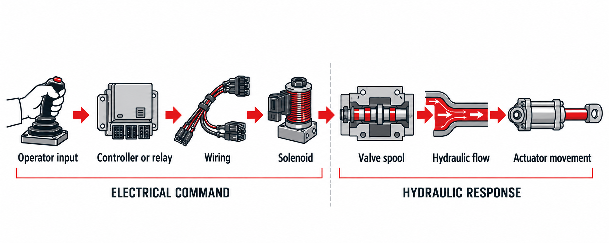
If an attachment will not raise, for example, several different failures could be responsible:
- The joystick is not producing the expected signal.
- A safety interlock is preventing the command.
- A connector has corroded or a wire has broken.
- The solenoid coil is open, shorted, or receiving insufficient voltage.
- The solenoid operates, but the valve spool is stuck.
- Pilot pressure is unavailable.
- The pump is not delivering adequate flow.
- A relief valve is bypassing fluid.
- Internal leakage prevents the cylinder from developing force.
This overlap is why “it sounds electrical” or “it feels hydraulic” is not a diagnosis. Even fault codes require interpretation. A code may identify an abnormal circuit or sensor value without proving which component caused it.
Symptoms can help establish a starting point, but each clue should be confirmed with a test.
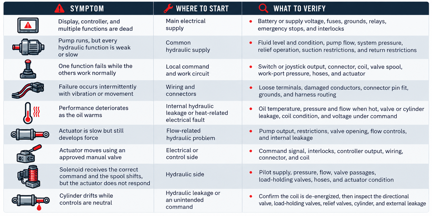
Electrical failures are often associated with abrupt or intermittent operation, warning messages, communication faults, or one function failing after a switch is activated. Hydraulic problems more often appear as weak force, slow movement, heat, noise, leakage, or performance that changes with load.
Those patterns are useful, but neither is universal. A loose electrical connection can fail consistently, while contaminated hydraulic valving can stick intermittently.
A Step-by-Step Diagnostic Process
1. Record the Failure Before Resetting Anything
Begin with the operator’s description and the conditions present when the problem occurred:
- Which function failed?
- Did it stop suddenly or deteriorate gradually?
- Was the equipment cold or at operating temperature?
- Does the failure occur under load, at a particular position, or after a certain sequence?
- Do other functions still work?
- Were any alarms, fault codes, unusual noises, leaks, or odors present?
- Was maintenance or wiring work performed recently?
Capture active and stored fault codes before disconnecting power or clearing the controller. Also record fluid temperature, engine or motor speed, operating mode, and other relevant conditions. An intermittent fault may disappear before the technician reaches the machine.
2. Control Every Energy Source
Hydraulic equipment can retain dangerous energy after the engine or electric motor is stopped. Suspended loads, charged accumulators, trapped fluid pressure, electrical power, and mechanical motion must all be addressed.
Before disconnecting wiring, removing a valve, or opening a hydraulic connection:
- Lower or mechanically support raised equipment.
- Shut down the machine according to its instructions.
- Follow the employer’s equipment-specific lockout/tagout procedure.
- Isolate electrical and hydraulic energy.
- Relieve stored pressure according to the manufacturer’s procedure.
- Discharge accumulators using the prescribed method.
- Verify the zero-energy state before beginning service.
OSHA’s hazardous-energy guidance specifically includes electrical, hydraulic, mechanical, pneumatic, and other energy sources. Never use your hand to search for a hydraulic leak; high-pressure fluid injection is a medical emergency.
Some diagnostic measurements require an energized machine. Those tests should be performed only by trained personnel using the equipment manufacturer’s procedure, suitable instruments, and controls that protect everyone from unexpected movement.
3. Use Both the Electrical and Hydraulic Schematics
The electrical diagram shows what must happen before the controller energizes the output. The hydraulic schematic shows what should happen after the valve shifts.
Trace the entire affected function:
- Start with the switch, joystick, or controller input.
- Identify relevant emergency stops, limit switches, neutral switches, and other permissives.
- Follow the output circuit to the solenoid or proportional-valve electronics.
- Locate the corresponding valve on the hydraulic schematic.
- Trace the pressure, pilot, work, drain, and return paths.
- Identify the component responsible for holding or moving the load.
A schematic turns troubleshooting into a sequence of testable conditions. Without one, technicians may need to trace the physical system before meaningful isolation can begin.
4. Determine the Scope of the Failure
Before testing individual components, ask whether the fault affects one function or the entire machine.
If several unrelated hydraulic functions are weak, look for something they share, such as the pump, reservoir, suction circuit, main relief valve, system-enable signal, controller power, or common ground.
If only one function has failed, focus on its local input, wiring, coil, valve section, hoses, and actuator. This simple division can prevent unnecessary testing across the whole machine.
5. Perform a Visual Inspection
Check the accessible, easily verified conditions first.
On the electrical side, inspect for:
- Loose, corroded, wet, or heat-damaged connectors
- Backed-out or bent terminals
- Chafed, pinched, or stretched wiring
- Poor ground connections
- Blown fuses or tripped protective devices
- Damaged sensors or switches
- Signs of an overheated solenoid coil
On the hydraulic side, inspect for:
- Low, aerated, contaminated, or overheated fluid
- Restricted or collapsed hoses
- External leakage
- Damaged filters or restriction indicators
- Loose pump couplings
- Abnormal vibration, cavitation, or mechanical binding
- Metal or other debris in the oil or filter
Do not replace a fuse and assume the problem is solved. A blown fuse is evidence of an overcurrent condition that still needs a cause.
6. Verify the Electrical Command at the Valve
The solenoid-operated valve is often the best dividing point between the two systems.
When the function is commanded, determine whether the solenoid receives the voltage or current specified by the manufacturer. Measure at the valve connector with the circuit connected and operating under its normal electrical load when the manufacturer’s procedure permits. An unloaded circuit can appear healthy even though excessive resistance causes voltage to collapse when current flows.
Verify both the supply and return paths. A good voltage reading to chassis ground does not necessarily prove that the coil has a sound ground or return circuit.
With power isolated and the coil disconnected, a technician may also check coil resistance or continuity against the manufacturer’s specification. An open circuit can indicate a broken winding, while abnormally low resistance can indicate a shorted winding. Exact acceptable values vary by coil design and temperature, so a generic resistance value should not be used.
Also remember that a controller may intentionally withhold the output because an interlock or sensor condition has not been satisfied. Never bypass a safety circuit simply to make the function operate.
7. Use a Manual Override Only When Authorized
Some directional valves include a manual override. When the manufacturer allows its use, it can help separate an upstream control problem from a downstream hydraulic problem.
- If the function operates normally with the manual override but not with the electrical command, investigate the input device, controller logic, interlocks, wiring, connector, and coil.
- If the function still does not operate, investigate the spool, pilot circuit, hydraulic supply, work circuit, actuator, load, and mechanical condition.
This is not an absolute verdict. A partial spool shift, inadequate pilot pressure, or a load-dependent failure can complicate the result.
A manual override may also bypass normal interlocks and cause immediate equipment movement. Use it only under the OEM procedure, with the work area controlled and personnel clear of hazards.
8. Measure Hydraulic Pressure and Flow
Hearing the pump run does not prove it is delivering the required hydraulic power. Likewise, seeing pressure on a gauge does not prove adequate flow is reaching the actuator.
Use the manufacturer’s specified test points and expected values to check:
- Pump inlet condition
- Pump outlet flow
- Standby and working pressure
- Pressure before and after the directional valve
- Pilot pressure
- Work-port pressure
- Return-line backpressure
- Pressure and flow with the oil at operating temperature
- Internal leakage where an approved test exists
Pressure represents resistance to flow; it does not, by itself, establish pump condition. A system may show low pressure because the pump is worn, a relief valve is open, a valve is not shifting fully, or fluid is escaping through internal leakage. Flow testing and pressure readings taken at carefully selected points help distinguish those possibilities.
All gauges, hoses, fittings, and flowmeters must be rated for the system and installed according to approved procedures.
Common Diagnostic Mistakes
Replacing the Most Obvious Component
A failed function does not automatically mean the cylinder, pump, solenoid, or directional valve has failed. Test the suspected component or circuit before ordering a replacement.
Trusting an Indicator Light Alone
An LED may confirm that a connector received some electrical signal. It does not prove the correct voltage or current reached the coil under load, nor does it prove the spool shifted completely.
Ignoring the Ground or Return Path
Technicians often test the positive supply and overlook corrosion or resistance on the return side. Both sides of the circuit must carry the required current.
Assuming a Click Means the Valve Worked
A click indicates magnetic or mechanical activity, but the spool may have moved only partially. Debris, blocked pilot passages, distorted valve bodies, or inadequate pilot pressure can prevent full shifting.
Adjusting Valves Before Measuring
Changing a relief, flow-control, or compensator setting can conceal the original failure and create a new hazard. Record existing settings and compare measurements with manufacturer specifications before making adjustments.
Changing Several Things at Once
Replacing multiple components or changing several settings destroys valuable diagnostic evidence. Make one controlled change, record it, and retest.
Confirm the Repair and Find the Root Cause
After correcting the fault, operate the complete function through its normal range and under representative working conditions. Verify:
- Correct direction and sequence
- Normal speed and force
- Stable system pressure and temperature
- Proper operation of interlocks and protective devices
- No external leakage or abnormal noise
- No recurring fault codes
- Correct neutral and load-holding behavior
Then ask why the component failed. A burned coil may have been subjected to low voltage, excessive voltage, an incomplete spool stroke, or improper duty. A stuck valve may point to contamination. A damaged wire may indicate poor routing or inadequate strain relief.
Correcting that underlying condition is what prevents the same downtime from returning.
Diagnose the Boundary Before Replacing Parts
The fastest route to a reliable repair is usually through the point where the electrical command becomes hydraulic action.
Confirm the command. Confirm the valve response. Measure pressure and flow. At every stage, compare what the system is doing with what its schematics and manufacturer documentation say it should do.
That process does more than separate an electrical problem from a hydraulic one. It identifies the specific failure, preserves useful evidence, and helps maintenance teams correct the cause instead of repeatedly treating the symptom.
For application-specific component information, Bailey’s technical resources and support teams can help you review hydraulic and electronic-control requirements. Have the equipment model, component identification, schematic, operating conditions, measurements, and fault history available before requesting guidance.


Shop
Hydraulics & Electronics
Bailey produces the highest quality hydraulic and electronic parts for diverse applications including manufacturing, automotive, construction, agriculture, forestry and OEM.


SKU: 325052


Build With Bailey
Custom hydraulic solutions designed to meet your unique needs. From expert engineering support to a wide range of components, we streamline your project from design to delivery.