
Powering Knowledge: Bailey Blog
Powering Knowledge: Bailey Blog
At Bailey, we know that knowledge fuels innovation. Our blog is your go-to resource for expert insights, industry trends, and practical guides—helping you stay ahead in hydraulics and electronic solutions.
At Bailey, we know that knowledge fuels innovation. Our blog is your go-to resource for expert insights, industry trends, and practical guides—helping you stay ahead in hydraulics and electronic solutions.
For OEM manufacturers, hydraulic component selection is an engineering decision, a reliability decision, and ultimately a customer experience decision.
The wrong component can create inefficiencies and damage customer confidence. The right component, however, can improve performance and help OEMs deliver equipment that consistently performs under demanding conditions.
So how do manufacturers make the right choice?
Start With the Application, Not the Component
One of the most common mistakes in hydraulic system design is focusing on individual products before fully understanding the application's requirements.
Before selecting cylinders, pumps, valves, or power units, manufacturers should evaluate:
- Operating pressure requirements
- Flow rate demands
- Load capacities
- Duty cycles
- Environmental conditions
- Available installation space
- Regulatory or safety requirements
A hydraulic system designed for material handling equipment faces very different challenges than one used in construction or industrial manufacturing.
The question should never be, "Which hydraulic component should we buy?"
The better question is, "What does the equipment need to achieve?"
Once that answer is clear, component selection becomes far more strategic.
Understand How Components Work Together
Hydraulic systems are ecosystems. Every component influences the performance of the others.
A high-performance cylinder cannot compensate for an undersized pump. A premium valve cannot overcome contamination caused by poor filtration. Even the most advanced hydraulic system will struggle if flow rates, pressure ratings, and operating conditions are mismatched.
Successful OEMs evaluate hydraulic systems as complete operating environments rather than collections of individual parts.
The goal is not simply selecting quality components. The goal is selecting components that function together efficiently and reliably throughout the equipment's lifecycle.
Focus on Performance Requirements First
Every hydraulic component has operational limits. Exceeding them often leads to premature failure.
When evaluating hydraulic components, OEMs should pay particular attention to:
Pressure Ratings
Components must be capable of handling both normal operating pressures and potential pressure spikes. Industry experts commonly recommend building in an adequate safety margin rather than selecting components that merely meet minimum operating requirements.
Flow Requirements
Flow directly impacts equipment speed and responsiveness. An incorrectly sized pump can create bottlenecks that reduce productivity and increase energy consumption.
Duty Cycle
Will the equipment operate intermittently or continuously? Components that perform well in light-duty applications may not withstand demanding, high-cycle environments.
Environmental Conditions
Extreme temperatures, moisture, dirt, vibration, and chemical exposure all influence component longevity. Components should be selected for the environments where equipment will actually operate.
Reliability Is Often More Valuable Than Maximum Performance
Many OEMs fall into the trap of prioritizing maximum specifications.
Higher pressure ratings. Higher flow capacities. More advanced features.
But customers rarely purchase equipment because a component has the highest specification on paper.
They purchase equipment because it works consistently.
Reliability often creates greater long-term value than peak performance.
A hydraulic system that operates efficiently for years with minimal downtime typically delivers a stronger return on investment than one designed solely to maximize output.
Consider Serviceability and Maintenance Early
The best hydraulic systems are designed with maintenance in mind from the beginning.
OEMs should evaluate questions such as:
- Are replacement components readily available?
- Can technicians easily access service points?
- Are filtration systems easy to inspect and replace?
- Are standard components available across multiple machine models?
Maintenance considerations often receive less attention during design phases, yet they significantly influence equipment ownership costs.
Customers remember how easy equipment is to maintain just as much as they remember how well it performs.
Don't Overlook Supplier Expertise
Hydraulic component selection has become increasingly complex as equipment demands continue to evolve, which is why component suppliers should be viewed as strategic partners rather than transactional vendors.
Experienced hydraulic suppliers can help manufacturers evaluate application requirements and identify compatibility issues.
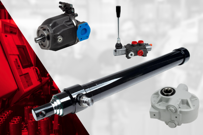
Every pump, valve, cylinder, hose, and fitting contributes to overall system performance. When those components are selected strategically, OEMs gain a competitive advantage.
The most successful manufacturers understand that hydraulic components are not just parts inside a machine. They are critical building blocks of equipment reliability, customer satisfaction, and long-term business growth.
Choosing the right hydraulic components is about engineering confidence into every machine that leaves the production floor.
Talk with a Bailey equipment specialist today. We'll help you identify the right hydraulic and/ or electronic components, optimize system performance, and engineer solutions that give your equipment a competitive advantage in the field.
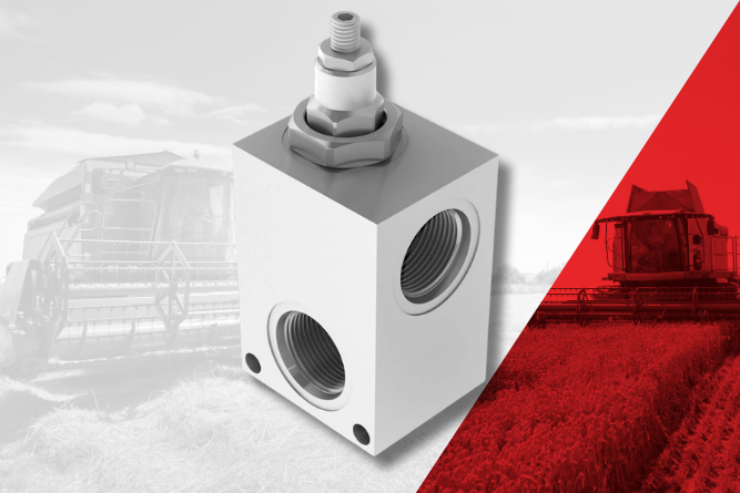
Choosing the Right Hydraulic Components for OEM Equipment
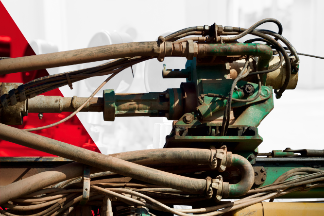
When a pump begins to fail, performance issues can quickly spread throughout your equipment, including overheating, slow operation, loss of pressure, unusual noise, or complete system shutdown.
Replacing a damaged hydraulic pump requires careful inspection, system cleaning, proper installation, and post-installation testing to prevent repeat failures and unnecessary downtime.
This guide will walk you through the essential steps for replacing a hydraulic pump safely and correctly.
Signs Your Hydraulic Pump Needs Replacement
Before replacing a pump, it’s important to confirm the pump is actually the source of the issue. Common symptoms of pump failure include:
- Excessive noise or whining
- Slow or erratic actuator movement
- Reduced hydraulic pressure
- Fluid overheating
- Visible leaks around the pump housing
- Metal contamination in hydraulic fluid
- Cavitation or vibration
- Loss of efficiency under load
In many cases, contamination, overheating, or improper fluid levels can actually contribute to pump failure. Identifying the root cause before installing a new pump helps prevent repeated damage.
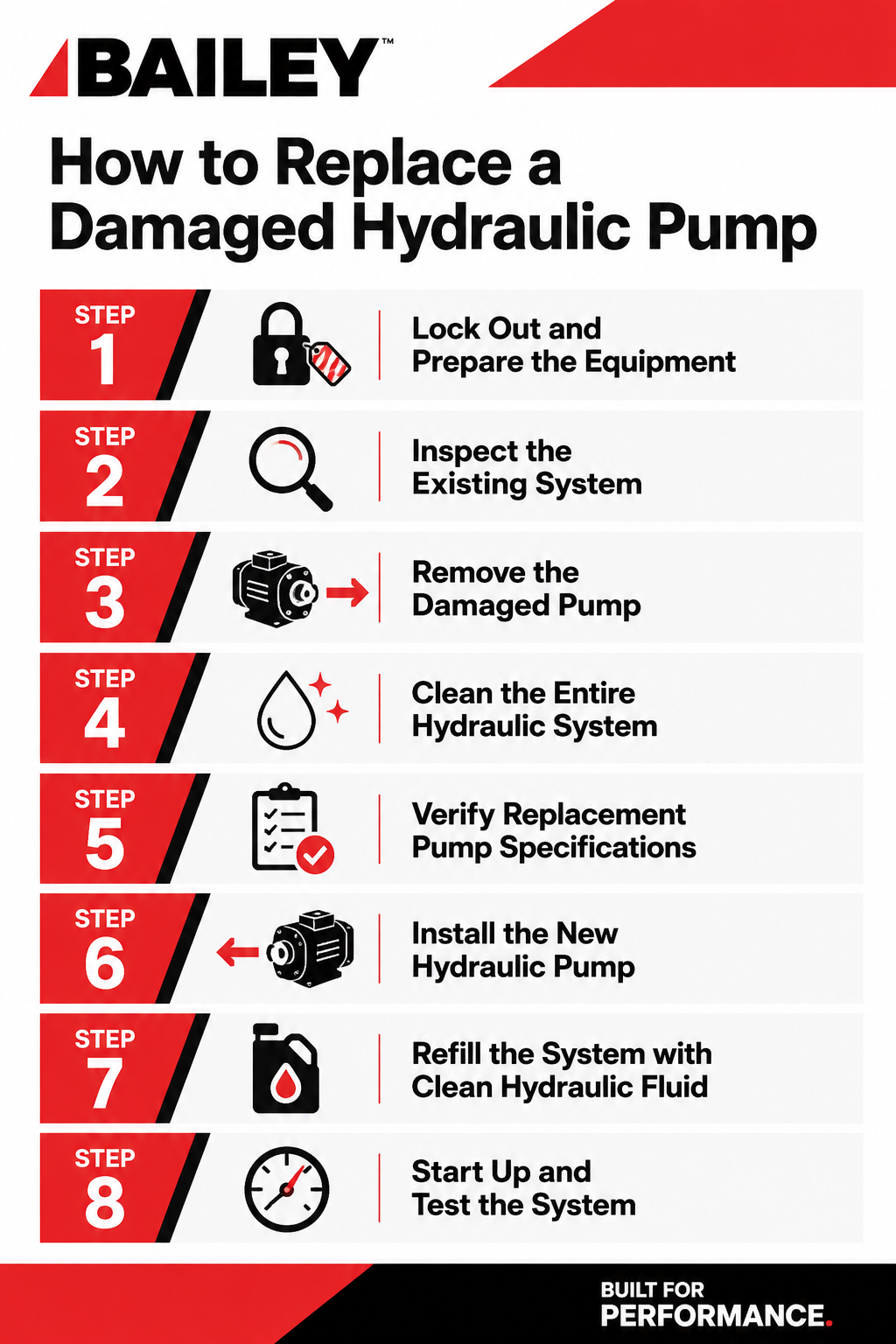
Step 1: Lock Out and Prepare the Equipment
Safety should always come first.
Before beginning any hydraulic pump replacement:
- Shut down the machine completely
- Relieve hydraulic system pressure
- Disconnect power sources
- Follow all lockout/tagout procedures
- Allow components and fluid to cool
Hydraulic systems can retain pressure even after shutdown, so never loosen fittings until pressure has been fully relieved.
Step 2: Inspect the Existing System
A failed pump is often the result of another issue within the hydraulic system. Before removing the old pump, inspect:
- Hydraulic fluid condition
- Reservoir cleanliness
- Suction lines and fittings
- Filters and strainers
- Relief valve settings
- Couplings and shafts
- Hose condition
Contaminated fluid is one of the leading causes of hydraulic pump damage. Dirt, metal particles, moisture, and degraded oil can quickly destroy a replacement pump if the system is not cleaned thoroughly.
Step 3: Remove the Damaged Pump
Once the system has been inspected:
- Drain hydraulic fluid if necessary
- Label and disconnect hydraulic lines
- Remove mounting hardware
- Disconnect the drive coupling or PTO
- Carefully remove the damaged pump
During removal, inspect the old pump for signs of:
- Scoring
- Excessive wear
- Burnt fluid residue
- Shaft damage
- Seal failure
These clues can help identify what caused the failure.
Step 4: Clean the Entire Hydraulic System
This step is critical.
Installing a new hydraulic pump into a contaminated system can lead to immediate damage and shortened pump life. Best practices include:
- Flushing hydraulic lines
- Cleaning the reservoir
- Replacing filters
- Inspecting suction strainers
- Removing debris from hoses and fittings
We strongly recommend fully cleaning the system before installing a replacement pump.
Step 5: Verify Replacement Pump Specifications
Not all hydraulic pumps are interchangeable.
Before installation, confirm the replacement pump matches the original system requirements, including:
- Flow rate (GPM)
- Pressure rating
- Rotation direction
- Mounting style
- Shaft configuration
- Port sizes
- Displacement
Using an incorrectly sized pump can create performance issues, excessive heat, or even premature failure.
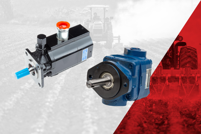
At Bailey International, we offer a wide range of hydraulic pump solutions, including gear pumps, piston pumps, vane pumps, hand pumps, and two-stage pumps designed for mobile hydraulic applications.
Step 6: Install the New Hydraulic Pump
When installing the replacement pump:
- Pre-fill the pump with clean hydraulic fluid if recommended
- Align shafts and couplings properly
- Secure mounting hardware evenly
- Reconnect hydraulic lines carefully
- Ensure all fittings are properly tightened
Improper alignment can place excess stress on bearings and seals, reducing pump life.
It’s also important to ensure the pump has an unobstructed oil supply during startup to prevent dry running or cavitation.
Step 7: Refill the System with Clean Hydraulic Fluid
Always use clean hydraulic oil with the correct viscosity recommended for the application.
After refilling:
- Bleed air from the system
- Check fluid levels
- Inspect for leaks
- Replace filters if needed
Air trapped in hydraulic systems can cause erratic performance and cavitation.
Step 8: Start Up and Test the System
Initial startup should be performed gradually.
Recommended startup procedure:
- Run the system at low RPM first
- Monitor pressure gauges
- Watch for leaks or unusual noises
- Cycle cylinders and motors slowly
- Recheck fluid levels
Pressure settings should always remain within the limits of the lowest-rated component in the hydraulic system.
Common Mistakes to Avoid
When replacing a hydraulic pump, avoid these common errors:
- Reusing contaminated hydraulic fluid
- Failing to replace filters
- Installing the wrong pump size
- Ignoring suction line restrictions
- Running the pump dry at startup
- Overlooking relief valve settings
- Skipping system flushing
Many repeat pump failures are caused by unresolved system contamination or installation issues.
Preventing Future Hydraulic Pump Failures
Preventive maintenance plays a major role in extending hydraulic pump life. Key maintenance practices include:
- Monitoring fluid cleanliness
- Replacing filters regularly
- Checking fluid levels
- Inspecting hoses and fittings
- Monitoring operating temperatures
- Addressing leaks immediately
Routine inspections help identify issues before they become costly failures.
Replacing a damaged hydraulic pump is really an opportunity to improve the reliability, efficiency, and longevity of your entire hydraulic system. By identifying the root cause of failure, thoroughly cleaning the system, and installing the correct replacement pump, operators can reduce downtime and avoid repeat failures.
At Bailey, we understand that every minute of downtime impacts productivity. That’s why we offer a comprehensive selection of hydraulic pumps, motors, cylinders, valves, reservoirs, and power units backed by knowledgeable hydraulic experts who can help you find the right solution for your application.
Whether you’re replacing a failed pump, upgrading your hydraulic system, or sourcing hard-to-find components, Bailey International is ready to help.
Explore our full line of hydraulic pumps or contact our team today to get expert support for your next hydraulic repair or replacement project.
How to Replace a Damaged Hydraulic Pump
At Bailey, we want to keep you moving forward, always. So, we’ve decided to highlight the most common hydraulic failures, and more importantly, how to prevent them through smart maintenance and component selection.
.png)
1. Fluid Contamination
The Problem:
Contaminants like dirt, metal particles, and water are the leading causes of hydraulic system failures. They accelerate wear, clog components, and reduce efficiency.
Prevention:
Implement strict filtration practices. Use high-quality filters and replace them on schedule. Store fluid properly, use clean transfer equipment, and regularly test fluid cleanliness. Sealed reservoirs and desiccant breathers can further reduce contamination risk.
2. Overheating
The Problem:
Excessive heat degrades hydraulic fluid, damages seals, and reduces system efficiency.
Prevention:
Maintain proper fluid levels and ensure cooling systems (heat exchangers, fans) are functioning correctly. Use the right viscosity fluid for your operating environment, and monitor system temperature regularly to catch issues early.
3. Improper Fluid Selection
The Problem:
Using the wrong hydraulic fluid can lead to poor lubrication, increased wear, and system inefficiency.
Prevention:
Always follow manufacturer recommendations for fluid type and viscosity. Consider operating temperature ranges and load conditions when selecting fluid. Periodic fluid analysis helps confirm performance and identify degradation.
4. Air Entrapment and Aeration
The Problem:
Air in the system causes erratic operation, noise, and increased oxidation of fluid.
Prevention:
Check for loose fittings, cracked hoses, and low fluid levels. Ensure proper reservoir design and return line placement to minimize turbulence. Bleed the system after maintenance to remove trapped air.
5. Seal Failure
The Problem:
Worn or damaged seals lead to leaks, contamination, and loss of pressure.
Prevention:
Inspect seals regularly for wear, hardening, or cracking. Use seals compatible with your hydraulic fluid and operating conditions. Avoid excessive heat and pressure spikes that can shorten seal life.
6. Hose and Fitting Failures
The Problem:
Hoses can crack, burst, or loosen over time, leading to leaks or sudden system failure.
Prevention:
Perform routine visual inspections for abrasion, bulging, or leaks. Make sure hoses are properly routed and secured to prevent rubbing or kinking. Replace hoses based on service life, not just visible damage.
7. Pump Failure
The Problem:
Hydraulic pumps can fail due to cavitation, contamination, or excessive wear.
Prevention:
Maintain proper inlet conditions to prevent cavitation. Check for adequate fluid supply and avoid restrictions. Keep fluid clean and monitor for unusual noise or vibration. Regularly check alignment and operating pressures.
8. Cylinder Drift or Leakage
The Problem:
Internal leakage in cylinders can cause drift, reducing precision and efficiency.
Prevention:
Check cylinder seals and rods for wear or scoring. Maintain clean fluid to prevent internal damage. Rebuild or replace cylinders showing signs of internal bypassing before failure worsens.
9. Valve Malfunction
The Problem:
Sticking or worn valves can disrupt flow control, leading to erratic system behavior.
Prevention:
Keep fluid clean and free of varnish buildup. Exercise valves periodically to prevent sticking. Inspect for wear and replace components as needed to maintain precise control.
Hydraulic failures don’t have to be inevitable. With the right components, proper system design, and a proactive maintenance strategy, you can significantly extend equipment life and reduce downtime.
At Bailey, we’re committed to delivering hydraulic solutions that keep your equipment and your business moving forward. Reach out to us today for a free consultation.
Moving Machinery Forward: How to Prevent the Most Common Hydraulic Failures
A faulty hydraulic pressure relief valve can bring operations to a grinding halt. This leads to costly downtime, missed deadlines, and potential safety hazards for your team. You rely on precise controls to keep your fleet operational, and understanding how to maintain these components is vital for long-term success.
This guide covers the essential steps for replacing a malfunctioning relief valve. We will explore how to identify the root cause of the failure, safely swap out the hardware, and source the ideal replacement to match your specific operational needs. By taking a proactive approach to maintenance, you can protect your equipment and keep your business moving forward.

The Fundamentals of Hydraulic Pressure Relief Valves
Before tearing down a machine, it helps to understand exactly what these components do. Pressure relief valves and safety valves are essential safeguards designed to keep hydraulic and pneumatic systems below a set pressure threshold.
Importance in Hydraulic Systems
A pressure relief valve remains normally closed during standard operations. If the system pressure builds above the maximum safety limit, the valve opens to dump excess fluid back to the reservoir tank. This simple mechanical action prevents extreme pressure build-up, which could otherwise rupture hoses, blow out seals, or cause catastrophic damage to the pump.
Types and Functions of Pressure Valves
Valves are generally categorized by their mode of operation. A pressure reducing valve is normally open and reduces the downstream pressure to a constant, predictable level whenever it exceeds a certain threshold. Conversely, a pressure relief valve is normally closed, which will relieve the pressure of the entire system.
Signs of a Faulty Pressure Relief Valve
When a valve begins to fail, the machine will usually provide warning signs. Common symptoms include:
- Failure to reach pressure: The system cannot achieve its designed target pressure, resulting in a production slowdown or a complete loss of lifting power.
- Over-pressurization: The system exceeds the maximum pressure limit, posing an immediate risk to the facility and equipment.
- Leakage: Hydraulic fluid escapes the system, which can cause severe overpressure conditions leading to system failure.
- Chattering: The valve opens and closes rapidly. This erratic behavior prevents the valve from operating correctly and often points to a blockage.
- Drifting cylinders: If a service-port relief valve is set too low, or if the poppet is failing to seat properly, the cylinder may creep or drift down under a load.
- Heat: If a relief valve prematurely relieves oil (not allowing the pressure to build to the actual setting value), the oil passing through this valve could generate more heat than expected.
Why and When to Replace Your Pressure Relief Valve
Valves do not last forever. Recognizing the common causes of failure helps you determine if a valve needs a simple adjustment, a thorough cleaning, or a complete replacement.
Common Causes of Failure
Contamination is the greatest enemy of hydraulic integrity. Dirt, water, and metal filings routinely cause significant damage to precision components. A piece of metal shaving the size of a grain of sand can prevent the valve poppet from seating, causing immediate pressure loss.
Wear and tear from years of service, damage from extreme temperature fluctuations, and wrong calibration also play major roles in valve degradation. If a pressure relief valve is calibrated to the wrong set pressure, it will release the fluid too early, rendering the machine effectively useless.
The Impact of a Failing Valve
A hydraulic system is totally dependent on its valves. Without them, pressure cannot be controlled. A failing valve severely hampers system performance, meaning mobile machinery cannot lift, push, or hold loads safely. In worst-case scenarios, a leaking relief valve can cause explosive overpressure conditions. Routine checks and immediate replacements are necessary to ensure total functionality.
Testing Methods
To confirm a valve is faulty, technicians use three primary testing methods:
- Bench testing: You shut down the system, remove the valve, and send it to a laboratory. This is the most thorough testing method, typically used during the manufacturing process.
- Inline testing: A trained technician calculates the setpoints while the valve remains in the system. This method eliminates the need for facility downtime and provides accurate, real-time reporting.
Step-by-Step Guide to Replacing a Hydraulic Pressure Relief Valve
Replacing a valve requires patience, mechanical knowledge, and the right tools. Always refer to your specific equipment's product manual, but you can generally follow these core steps.
Safety Precautions and Necessary Tools
Always shut down the system completely and relieve any trapped pressure before beginning work. Gather your combination wrenches and any specialized tools required for your specific machinery. Depending on the machine's design, you may need to modify standard tools. For instance, some mechanics cut a combination wrench in half and grind custom grooves to fit into tight gear case spaces.
Draining Fluid or Positioning Equipment
You must ensure hydraulic fluid does not spill everywhere when you remove the valve. You can fully drain the fluid, but strategic positioning sometimes offers a faster alternative. For example, when working on certain tractors, mechanics park the vehicle with one rear wheel on blocks. This tips the fluid to the opposite side of the gear case, keeping the workspace dry without requiring a massive fluid drain.
Removing the Old Valve
Locate the faulty valve. Depending on the equipment, you might need to remove side covers or power take-off (PTO) levers to access the area. In tight spaces, you may have to work purely by feeling. If you are using modified or short tools, tie a string around the wrench handle and loop the other end to your finger. This simple trick prevents you from dropping the wrench into the abyss of the machinery. Use the wrench to carefully unthread and remove the old component.
NOTE: You might want to have plugs/caps available so that when the valve is removed, the plug/cap can be installed to minimize fluid loss while the valve is no longer connected.
Installing the New Valve
Verify that your new valve matches the required specifications and thread sizes. Thread the new valve into the pump housing (if that’s where the problem has been identified) by hand to prevent cross-threading, then tighten it securely with your wrench. Double-check that all surrounding seals and mating surfaces are clean and free of debris.
Post-Replacement Checks and Calibration
Once the new valve is installed, you must calibrate it. Setting your hydraulic system relief pressure ensures the equipment runs efficiently without unnecessary strain.
To adjust the relief valve, loosen the jam nut. Turn the relief valve screw clockwise to increase the pressure, or counterclockwise to decrease it. For context, some heavy agricultural equipment requires an operating pressure of roughly 1800 PSI, but always check your manufacturer guidelines.
Tighten the jam nut to secure the screw, and then test the system. If the gauge reading stays too low, reinspect the valve or look for other contributing factors, such as blockages or a malfunctioning pump.
Choosing the Right Replacement Valve and Supplier
Standard controls often lack the adaptability to meet real-world operating conditions. Investing in the correct valve type prevents future breakdowns and ensures seamless integration with your existing setup.
Importance of Investing in the Correct Valve Type
Custom hydraulic controls address the gaps left by off-the-shelf parts. With custom designs, safety features can be tailored to match your specific operational risks. Choosing the exact right component ensures your equipment operates at peak efficiency.
What to Look for in a Hydraulic Supplier
You need more than just a parts vendor; you need a reliable partner. A good supplier offers high-quality components, constant supply on demand, and deep technical expertise. When you receive proper guidance during a replacement, you save money, time, and effort. Look for a supplier that understands the complexities of mobile hydraulics and can help troubleshoot difficult drift issues.
At Bailey International, we have five decades of expertise in providing custom hydraulic solutions tailored to the transportation, agriculture, and construction industries. Our engineering teams help you select and configure the exact components you need, ensuring optimal safety and performance from day one.
Hydraulic pressure relief valves are the unsung heroes of heavy machinery. By understanding the common causes of failure, running routine tests, and maintaining strict fluid hygiene, you can extend the life of your equipment. When replacement becomes necessary, choosing a high-quality, perfectly calibrated valve ensures your fleet remains strong, capable, and safe.
Complex hydraulic challenges require expert solutions. If you need technical advice, custom cylinder solutions, or high-quality replacement valves, partner with the experts. Explore Bailey International's custom hydraulic solutions today, and ensure your machinery is always ready for the heavy lifting.
How to Replace a Faulty Hydraulic Pressure Relief Valve
Longevity isn’t just a benefit in heavy machinery; it’s a necessity. At Bailey International, designing for longevity is embedded in everything we do.
Hydraulic systems' ability to deliver consistent power and controlled motion makes them ideal for demanding environments where durability is critical. Longevity in hydraulics starts with robust design of components that can withstand high pressures, heavy loads, and continuous operation without compromising performance.
At Bailey, longevity is engineered into every hydraulic solution. Whether it’s cylinders designed for up to 5,000 PSI or custom configurations for unique applications, each component is built with high-performance materials and precise specifications. From chrome-plated rods to integrated to intricate valve systems, these design choices reduce wear, improve efficiency, and extend operational life.
In fact, customization plays an essential role in longevity. Off-the-shelf solutions may work temporarily, but systems designed specifically for the environment they operate in deliver sustained performance. Our collaborative engineering approach ensures that hydraulic systems are not just functional, but optimized for long-term durability and reduced downtime.
Electronics Designed for Precision and Reliability
As machinery evolves, electronics are becoming as integral as hydraulics in achieving longevity. Electronic controls, such as joysticks, sensors, and control systems, enable operators to manage complex machinery with precision and consistency. This precision reduces operator error, minimizes mechanical strain, and ultimately extends the life of the entire system.
From rugged joystick controls to fully integrated electro-hydraulic solutions, each component is built to withstand real-world conditions while delivering intuitive, responsive control. By integrating electronics directly into system design, machines operate more efficiently, reducing unnecessary stress on hydraulic components and improving overall life-cycle performance.
Customization is once again the differentiator. Through Bailey’s Build Custom Program, electronic controls are tailored to the exact needs of the application, ensuring seamless integration with hydraulic systems and operator workflows. The result is smarter machinery that not only performs better today but continues to deliver value over time, adapting to evolving operational demands.

Building for What’s Next
Designing for longevity means thinking beyond immediate performance; it’s about creating solutions that stand the test of time. At Bailey, that commitment is reflected in our engineering expertise, custom solutions, and dedication to supporting our customers at every stage of their equipment life-cycle. From hydraulics that deliver consistent power to electronics that enhance precision and control, every solution is built to move your machinery forward.
Ready to design equipment that lasts? Partner with Bailey today to build custom hydraulic and electronic solutions engineered for longevity.
.png)
Moving Machinery Forward: Designing for Longevity
Mobile hydraulics is entering a defining moment. The systems themselves are more advanced than ever, but with that progress comes a new layer of complexity that is reshaping how OEMs design, build, and support equipment.
What’s emerging is not a single challenge, but a network of interconnected pressures. Each one influences the others. And together, they are forcing the industry to rethink long-standing assumptions about performance, cost, and capability.
Below are the five challenges that matter most right now.
1. Cost Pressure vs. System Complexity
Modern hydraulic systems are no longer purely mechanical. They are integrated ecosystems that combine:
- Sensors and embedded electronics
- Advanced control systems
- Software-driven diagnostics
This evolution unlocks significant performance gains, including greater precision, improved efficiency, and predictive maintenance capabilities. But it also introduces fundamental tension: capability comes at a cost.
The Core Challenge
Every layer of intelligence added to a system increases:
- Development costs
- Integration complexity
- Maintenance requirements
OEMs are now forced into a more strategic calculation: Does the performance gain justify the total cost of ownership?
Why It Matters
The answer is rarely straightforward. A more advanced system may reduce downtime and improve productivity, but if it requires specialized servicing or expensive components, the long-term economics can become difficult to justify.
The real shift: Cost is no longer just about upfront price. It’s also about life-cycle value.
2. The Skills and Talent Gap
As systems evolve, so do the skills required to build and maintain them. The traditional boundaries of hydraulic expertise are expanding.
Today’s engineers and technicians must operate at the intersection of:
- Hydraulics
- Electronics
- Software
- Controls engineering
The Core Challenge
The talent pipeline is not keeping pace with this convergence.
Organizations are struggling to find individuals who can:
- Diagnose both mechanical and digital system issues
- Integrate hardware with software-driven controls
- Adapt to rapidly evolving technologies
Why It Matters
This gap creates friction across the entire value chain, from design to field service.
A highly advanced system is only as effective as the people who support it.
The broader implication: Competitive advantage is shifting toward companies that can build and retain multidisciplinary teams.
3. Regulatory and Environmental Constraints
Global regulations are tightening, and they are doing so at an accelerating pace.
Hydraulic systems are now under scrutiny for:
- Emissions impact
- Fluid leaks and contamination
- Noise pollution
The Core Challenge
Compliance is no longer a box to check. It is a moving target that requires continuous innovation.
OEMs must redesign systems to:
- Improve efficiency
- Reduce environmental impact
- Meet evolving regional standards
Why It Matters
Regulation is forcing the industry to rethink system architecture, materials, and performance benchmarks.
The shift in mindset: Innovation is no longer optional. It is the cost of staying in the market.
4. Reliability vs. Innovation Tradeoff
Mobile hydraulic systems operate in some of the harshest environments imaginable. Think extreme temperatures, heavy loads, and constant vibration.
At the same time, the industry is pushing forward with:
- AI-driven diagnostics
- Electrification
- Advanced automation
The Core Challenge
New technologies must prove themselves under real-world conditions before they can be widely adopted.
This creates a natural tension:
- Innovation demands speed
- Reliability demands caution
Predictive AI models can identify failures before they occur. But in safety-critical applications, they must also be:
- Fully explainable
- Proven to be fail-safe
Until then, adoption will remain measured.
Why It Matters
The industry cannot afford to compromise on reliability, but delaying innovation carries its own risks.
The balancing act: Move forward without breaking trust.
5. Supply Chain and Component Availability
Even the most advanced system design is only as strong as its supply chain.
Mobile hydraulics is increasingly exposed to:
- Component shortages
- Supplier consolidation
- Global sourcing risks
This challenge is amplified by the growing reliance on:
- Electronic components
- Sensors
- Control units
The Core Challenge
As systems become more integrated, dependencies increase. A delay in one component can stall an entire production line.
Why It Matters
Supply chain instability doesn’t just impact timelines; it impacts strategic flexibility.
Companies must now think beyond cost and consider:
- Supplier resilience
- Geographic risk
- Long-term availability of critical components
The emerging priority: Build supply chains that are as robust as the systems they support.
How Bailey is Moving the Industry Forward
Challenges of this scale don’t get solved in isolation. They require collaboration across manufacturers, suppliers, and technology partners who understand both the technical and operational realities of mobile hydraulics.
This is where companies like Bailey International play a critical role.
By bridging deep hydraulic expertise with a forward-looking approach to system integration, Bailey helps OEMs navigate complexity, whether that’s sourcing hard-to-find components, supporting evolving system architectures, or enabling more efficient and reliable solutions at scale.
Connect with Bailey today to explore how the right hydraulic partner can help you simplify complexity, accelerate development, and deliver more reliable systems at scale.

Moving Industries Forward: Top 5 Mobile Hydraulic Trends in 2026
Most companies don’t set out to choose the wrong supplier. They compare pricing, check lead times, maybe skim product availability, and make a reasonable decision.
The problem is that most suppliers look good on paper.
The real difference shows up later. When a machine is down, when an order is wrong, when you need an answer now (not tomorrow).
That’s where the gap between a vendor and a partner becomes obvious.
If you’re sourcing hydraulic components, it’s worth asking a different question: not just who can supply this, but who actually supports how we operate?
“Good Enough” Suppliers
On the surface, many hydraulic suppliers offer similar things: Comparable parts, competitive pricing, acceptable delivery windows, etc.
But those similarities don’t hold up under pressure.
You start to notice delays in communication. You get routed through systems instead of talking to someone who knows your business. You spend time fixing mistakes that shouldn’t have happened in the first place.
None of these issues show up in a quote, but they show up quickly in your operations.
And over time, they cost far more than a small difference in price.
What It Means to Think in Terms of Partnership
Choosing a supplier through a partnership lens is less about features and more about experience.
It’s the difference between placing orders and actually being supported.
A true partner helps you move faster when something breaks. They help you avoid mistakes before they happen. They adjust to how your business runs instead of forcing you into rigid processes.
In practical terms, that changes how you evaluate suppliers.
Start With Responsiveness
In hydraulics, speed matters. Not just in shipping, but in communication.
When something goes wrong, you don’t need a ticket number. You need an answer.
A strong hydraulic supplier responds quickly to quotes, questions, and issues. More importantly, they make it easy to reach someone who can actually help.
That responsiveness directly impacts uptime, and uptime is where real cost savings live.
Focus on Expertise
A catalog doesn’t solve problems. People do.
The right supplier helps you choose the correct hydraulic components, troubleshoot issues, and navigate alternatives when something isn’t available. They don’t just process orders; they help you make better decisions.
That kind of support reduces risk and prevents costly missteps.
Pay Attention to How Flexible They Are
This is where many suppliers quickly fall short.
Large, volume-driven companies are often built around efficiency at scale. That usually means rigid minimums, standardized processes, and limited flexibility.
But most businesses don’t operate in perfect predictability.
A partner understands that, and they’re willing to work with smaller or variable orders, adjust to your timelines, and support the way your business actually runs.
That flexibility improves cash flow and removes friction from your day-to-day operations.
Relationships Should Feel Consistent, Not Transactional
If every interaction with your supplier feels like starting over, that’s a signal.
Strong partnerships are built on continuity. You want to work with people who know your business and can anticipate what’s coming next.
That familiarity speeds everything up, so you spend less time explaining and more time executing.
The Real Test
This is where the difference becomes impossible to ignore.
Delays happen. Supply chains shift. Parts become unavailable.
The question is how your supplier responds.
Do they communicate clearly, or leave you guessing? Do they help find solutions, or simply report problems? Do they take ownership, or push responsibility back onto you?
A true partner doesn’t disappear when things get complicated. They become more visible.
Choose a Supplier That Can Grow With You
Many businesses eventually hit a ceiling with their supplier. Either they’re too small to matter, or they outgrow the level of support they’re getting.
A partnership-focused supplier removes that concern.
They support you early, when flexibility matters most. And they continue to invest in the relationship as your business grows.
If you want to pressure-test your current setup, step back and ask:
When something urgent happens, do we get fast, useful responses?
Are we being guided toward better solutions or just sold what’s available?
Does our supplier adapt to us, or do we constantly adapt to them?
Do we feel like a priority?
The answers tend to be clear.
Choosing a hydraulic supplier isn’t just about sourcing parts. It’s also about shaping how your business runs under pressure.
The right partner helps you reduce downtime, avoid mistakes, and move with confidence, even when things don’t go as planned.
If that’s something you’re exploring, Bailey works with businesses facing exactly these kinds of challenges.
No pressure. Just a conversation to see if there’s a better fit.
How to Choose a Hydraulic Supplier
A drop in hydraulic performance often points directly to a malfunctioning suction line. The suction line is responsible for pulling hydraulic fluid from the reservoir to the pump. If this pathway fails, the pump can't generate the flow needed to operate your equipment.
A poorly functioning suction line forces the pump to work harder, leading to overheating, excessive noise, and eventual pump failure. Catching early warning signs like flattened hoses or small fluid leaks can save you from expensive repairs and hours of unnecessary labor.
Understanding how to identify and resolve the following suction problems is the key to completing your projects smoothly.
Understanding Cavitation and Pump Damage
Cavitation is a frequent and destructive issue in hydraulic systems. It happens when the pressure on the suction side of the pump drops below the fluid's vapor pressure. This sudden pressure drop causes the hydraulic fluid to boil and form small vapor bubbles. As these bubbles pass into the higher-pressure areas of the pump, they collapse with immense force.
This behavior causes significant internal damage. The collapsing bubbles erode the metal surfaces of pump components, eventually destroying impellers and housing walls. A pump experiencing cavitation will often sound like it has marbles or gravel rattling inside it.
To resolve cavitation safely, check your suction line for any constraints like clogged filters or undersized hoses. Clearing these blockages reduces the pressure drop at the suction side. You can also lower the pump speed to reduce the suction demand or increase the system pressure. Always ensure your setup meets the required fluid flow ratings to prevent vapor bubbles from forming in the first place.
Identifying Starvation and Air Leaks
Starvation occurs when the pump simply does not receive an adequate supply of hydraulic fluid. While cavitation involves vapor bubbles formed by low pressure, starvation usually stems from a physical lack of fluid or a blockage. Operating a starved pump leads to severe overheating and rapid wear of internal parts.
The most common cause of fluid starvation is an insufficient fluid level in the main reservoir. Regularly check your fluid tanks before starting a heavy agricultural project. If the fluid level drops below the suction inlet, the pump will draw in air. Blockages from dirt, grit, or debris built up from previous runs can also restrict fluid flow, choking the pump.
Air leaks in the suction line act as another major contributor to starvation. If a hose connection is loose or a seal is damaged, the vacuum effect will pull ambient air into the line rather than drawing fluid from the tank. You can spot an air leak by looking for foamy, aerated hydraulic fluid in the reservoir or listening for a whining noise from the pump. Thoroughly inspect all valves, connections, and fittings. Tighten loose clamps and replace any worn seals to maintain a perfectly airtight system.
Spotting Physical Hose Failures
Your hydraulic hoses face harsh environmental conditions, constant vibrations, and internal stress. Physical damage to the hose structure will quickly compromise suction performance.
Detecting Collapsed Hoses
A standard hydraulic hose is not always designed to handle the intense vacuum pull of a suction line. If you notice a flattened or deformed hose, it means the structure has collapsed under the vacuum pressure. This usually happens when users install a general-purpose hose instead of a dedicated suction hose.
A collapsed hose severely restricts fluid flow. To fix this, replace the flattened hose with a suction-specific hose featuring the correct vacuum rating. Hoses reinforced with spiral wire provide the strength needed to resist collapsing under negative pressure.
Cover Abrasion and Material Degradation
Cover abrasion occurs when a hose repeatedly rubs against vibrating machine parts or other hydraulic components. Over time, the outer rubber cover wears away, exposing the internal reinforcement layers. Once the wire or textile reinforcement is exposed, the hose is highly susceptible to rust and sudden failure.
Using incompatible hydraulic fluids causes a different type of physical damage known as tube swell. If the fluid chemicals break down the inner rubber lining, the inner tube will swell, blister, or delaminate. This restricts internal flow and sends rubber debris directly into the pump. To prevent physical damage, route hoses away from high-wear areas and install protective nylon sleeves. Always verify that your chosen hydraulic fluid is completely compatible with your hose material.
Resolving Connection and Coupling Issues
Even the highest quality suction hose will fail if the connections are not secure. Issues at the coupling interface lead to system-wide pressure losses and messy fluid leaks.
Troubleshooting Leaks at the Coupling Interface
Visible dripping or weeping of hydraulic fluid at the metal fitting typically points to a faulty seal. This is often caused by an over-crimped hose end, a missing O-ring, or the use of mismatched fittings. If the threads do not align perfectly, the seal will not hold.
If you find a leak at a connection point, don't overtighten the fitting. Overtightening can crush the O-ring and make the leak worse. Instead, turn off the equipment, release the pressure, and inspect the fitting. Replace any damaged O-rings and reassemble the connection using the manufacturer's recommended torque specifications. Ensuring your fittings match the hose dimensions perfectly guarantees a secure, leak-proof connection.
Preventing Coupling Blow-Off
Coupling blow-off is a serious failure where the metal fitting completely detaches from the end of the hose. While less common on the suction side than the high-pressure discharge side, it can still happen due to improper assembly or extreme pressure surges.
If a coupling blows off, the entire hose assembly must be replaced. Ensure the new hose is cut cleanly and crimped using the correct dies. Leaving a little extra slack in the hose length during installation is a smart practice. Hydraulic hoses can shrink slightly under pressure, and leaving some slack prevents pulling stress on the couplings.
Best Practices for Prevention and Maintenance
Preventing suction line failures requires consistency. A proactive maintenance routine keeps your equipment running efficiently and safely.
Visual inspections should be part of your normal project preparation. Look closely for surface cracks, soft spots, twists, or small leaks before you begin your day. Even a minor twist during installation can severely reduce a hose's service life. Always align your hoses properly using the printed layline as a visual guide so they bend naturally without twisting.
Proper storage extends component life significantly. Keep spare hoses coiled gently in cool, shaded spaces away from direct sunlight and extreme heat. Exposure to UV rays and high temperatures accelerates the breakdown of rubber compounds.
When you face a challenging installation or cannot pinpoint the source of a suction drop, defer to expert guidance. Reaching out to Bailey's Technical Support Team provides you with free, expert advice tailored to your specific setup. Speaking with professionals ensures your components integrate seamlessly with your existing systems, saving you time and frustration.
Ensuring Long-Term System Reliability
When a suction line collapses or starts leaking, you might be tempted to apply a temporary patch or wrap it in heavy-duty tape. Patching a hydraulic hose is dangerous and ineffective. The vacuum pressure will easily bypass a temporary fix, pulling air into the system and causing further pump damage.
For reliable, long-lasting performance, damaged suction lines must be replaced entirely. Choosing durable, high-quality hydraulic components is an investment in your equipment's longevity. A custom-fit, properly rated suction hose eliminates the constant worry of unexpected breakdowns.
Take the time to evaluate your current hydraulic system today. If your equipment feels sluggish, inspect the suction line using the steps outlined above. For a seamless integration and expert help selecting the perfect replacement parts, connect with the Bailey team. Our cost-effective, easily installed solutions will get your machinery back to peak efficiency, allowing you to finish your projects with confidence.

How to Fix Common Suction Line Failures Safely and Easily
Mobile equipment manufacturers face an ongoing challenge: how to deliver precise hydraulic control while managing increasingly complex operational requirements. Traditional relay-based control systems served their purpose for decades, but they come with significant limitations like bulky installations, multiple failure points, difficult troubleshooting, and limited flexibility for customization.
Driver boards represent a fundamental shift in how mobile equipment control systems are designed and implemented. These compact electronic solutions consolidate the functions of multiple relays, timers, and logic circuits into single, programmable units that deliver superior performance and reliability.
From Relays to Driver Boards
Each relay in a relay-based control system represents a potential failure point, and troubleshooting complex relay logic can consume hours of technician time. When modifications are needed, the entire system may require rewiring.
Driver boards eliminate these complications. By integrating control logic into solid-state electronics with factory programming, manufacturers gain several immediate advantages:
Simplified Installation: A single driver board replaces multiple relays and timers, reducing wiring complexity and installation time. Fewer connections mean fewer opportunities for wiring errors or connection failures.
Enhanced Reliability: Solid-state outputs withstand the vibration, temperature extremes, and electrical transients common in mobile equipment environments. Built-in protection features guard against over-current, over-temperature, and switching transients that would damage traditional relay systems.
Customizable Logic: Factory programming allows manufacturers to implement complex control sequences that would require dozens of relays and timers. Changes to control logic can be made through reprogramming rather than physical rewiring.
Reduced Footprint: Compact driver boards fit in tight spaces where relay panels would never work, supporting modern equipment designs with limited available space for control components.
Modern driver boards offer capabilities that extend far beyond simple relay replacement. Bailey's driver board portfolio demonstrates the range of functions these solutions provide:
The DBL-17 Logic Driver Board handles complex control requirements by reading up to 10 inputs and controlling up to 17 high-current outputs. This capability allows a single control handle to manage multiple hydraulic functions through programmable logic sequences. The board's solid-state outputs can be paralleled for higher current requirements, and comprehensive protection features ensure reliable operation in demanding applications.
Danfoss Adapter Driver Boards specialize in proportional control, enabling direct connection between joystick controls and industry-standard proportional valves. These boards provide the signal conditioning and amplification needed for precise valve control, with features like 300ms ramp rates that ensure smooth, controlled movements. The availability of Caterpillar ECM compatible versions demonstrates how driver boards can integrate with existing equipment architectures.
The Single Axis Driver Board (SDB-P1) focuses on proportional solenoid control, supporting applications where precise positioning or speed control is required. With adjustable PWM outputs up to 2.5A and dual 7-segment displays for field calibration, this board provides the flexibility technicians need for optimal system tuning.
Protection Features
Mobile equipment operates in harsh environments where electrical disturbances are common. Driver boards incorporate protection features that would be impractical to implement with relay-based systems:
- Over-Current Protection: Automatic current limiting prevents damage from short circuits or overloaded outputs, eliminating the need for external fuses on each circuit.
- Thermal Management: Built-in temperature monitoring shuts down outputs before heat damage occurs, then automatically resets when temperatures return to safe levels.
- Transient Protection: Solid-state designs withstand voltage spikes from inductive loads, eliminating the arcing and contact wear that degrades relay performance over time.
- Reverse Polarity Protection: Prevents damage from incorrect power connections during installation or maintenance, a common issue in field service situations.
- Fault Detection: Status indicators and diagnostic features help technicians quickly identify and resolve issues, reducing downtime and service costs.
Factory Configuration for Your Specifications
One of driver boards' most significant advantages is factory programming that matches your exact requirements. Rather than selecting from limited off-the-shelf options, manufacturers work with engineering teams to define:
- Input signal types and voltage ranges
- Output current requirements and PWM frequencies
- Control logic sequences and timing parameters
- Fault response behaviors
- Enable/disable functions and interlocks
This customization ensures the driver board integrates seamlessly with your equipment design without requiring external components or workarounds. Changes to control logic can be implemented through programming updates rather than hardware modifications.
Integration with Proportional Control Systems
Proportional hydraulic control has become standard in modern mobile equipment, offering the precise positioning and speed control operators demand. Driver boards designed for proportional applications provide critical functions:
- Signal Conditioning: Converting joystick outputs to the voltage ranges proportional valves require, with precise calibration to ensure consistent performance across equipment units.
- Ramp Control: Managing acceleration and deceleration rates to prevent jerky movements and improve operator comfort while protecting hydraulic components from shock loads.
- Valve Enable Control: High-current outputs for valve energization, coordinated with proportional signals to ensure proper valve operation.
- Fault Management: Monitoring for open circuits, short circuits, or out-of-range signals that indicate system problems requiring attention.
Real-World Application Considerations
Successful driver board implementation requires attention to several practical factors:
Supply Voltage Range: Mobile equipment may operate on 12V or 24V electrical systems, and voltage can vary significantly during starting and charging. Driver boards with wide supply voltage ranges (+6V to +30V) handle these variations without external regulation.
Environmental Sealing: While driver boards themselves are typically housed in protective enclosures, connector selection and sealing methods must prevent moisture and contamination ingress in harsh operating environments.
EMI Considerations: Mobile equipment often includes radio communications, GPS, and other electronic systems sensitive to electromagnetic interference. Proper driver board grounding and shielding prevents interference issues.
Heat Dissipation: High-current outputs generate heat that must be managed through proper mounting and ventilation. Understanding thermal requirements during installation prevents performance degradation.
Field Serviceability: While driver boards reduce overall system complexity, providing clear documentation and diagnostic procedures helps service technicians maintain equipment efficiently.
Beyond technical advantages, driver boards deliver measurable business benefits:
- Reduced Assembly Time: Simplified wiring and fewer components accelerate production line throughput, reducing labor costs per unit.
- Lower Warranty Costs: Enhanced reliability and protection features reduce field failures and warranty claims.
- Improved Product Quality: Consistent factory programming eliminates variability between units and reduces quality issues from wiring errors.
- Easier Updates: Design improvements can be implemented through programming changes rather than hardware modifications, supporting continuous improvement initiatives.
- Enhanced Customer Satisfaction: More reliable control systems reduce customer downtime and maintenance costs, strengthening your reputation and customer relationships.
Selecting the Right Driver Board
Choosing appropriate driver boards for your equipment requires careful evaluation of:
- Number and type of inputs needed
- Output current and voltage requirements
- Control logic complexity
- Environmental conditions
- Integration with existing electrical architecture
- Future expandability needs
Working with experienced suppliers, like Bailey, who offer engineering support ensures proper selection and successful implementation. Technical documentation, including detailed specifications and wiring diagrams, supports both production and field service requirements.
Manufacturers who integrate driver boards into their designs gain competitive advantages through reduced production costs and enhanced equipment capabilities. The technology has matured to the point where driver boards should be the default choice for new equipment designs and a priority upgrade for existing product lines experiencing reliability issues with relay-based systems.
Bailey's specialized driver boards are designed specifically for mobile equipment applications, with factory configuration services and technical support that ensure successful integration. Our engineering team works with manufacturers to define optimal solutions for their specific requirements, backed by rapid delivery from our distribution network.
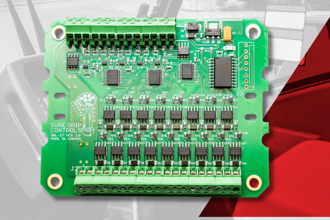
Why Driver Boards Are Essential for Modern Mobile Equipment Control Systems
Imagine operating a crane or an excavator, and you notice the boom slowly descending on its own, inches at a time, even though your hands are off the controls. This phenomenon, known as hydraulic cylinder drift, is more than just an operational annoyance. It represents a significant safety hazard, a loss of precision, and a drain on your equipment’s efficiency.
For professionals in construction, agriculture, forestry, and on-road trucking, equipment reliability is non-negotiable. When a cylinder drifts, it means the hydraulic fluid that creates the force to hold a load is escaping somewhere it shouldn’t. Whether it's a slow "creep" that hinders precision work or a rapid descent that endangers personnel, the issue requires immediate attention.
However, diagnosing the root cause isn't always straightforward. Many technicians immediately blame the piston seals, but the physics of hydraulic systems suggests the problem is often more complex.
Understanding the Mechanics of Drift
To fix the problem, you first need to understand what is happening inside the barrel. Hydraulic cylinder drift is defined as the unintentional movement of a cylinder when it is supposed to be held in a static position by directional control valves, check valves, or counterbalance valves.
Drift is essentially the loss of "hydraulic lock." In a healthy system, the fluid trapped between the piston and the valve creates a solid column of oil that supports the load. Because hydraulic fluid is virtually incompressible, the load should remain stationary. When the cylinder moves uncommanded, that fluid is going somewhere. It is either internally leaking across the piston, through a valve in the system, or externally out of the system.
While it's easy to spot a pool of oil on the ground, internal leaks are the silent killers. They allow pressure to equalize or bleed off, defeating the hydraulic lock and causing the load to drop.
The Primary Causes of Cylinder Drift
While every hydraulic system has unique variables, drift usually stems from one of three main categories: internal sealing failures, valve issues, or external environmental factors.
1. Internal Leakage and the Piston Seal Myth
There is a common misconception in the industry that if a piston seal leaks, the cylinder will automatically drift down. This isn't necessarily accurate.
If a double-acting cylinder’s ports are blocked (holding a load) and the piston seal leaks, fluid moves from the high-pressure side to the low-pressure side. However, once the pressure equalizes on both sides of the piston, the cylinder effectively becomes hydraulically locked again. The cylinder might settle slightly as the pressure balances, but it shouldn't continue to drift indefinitely unless fluid can escape the cylinder entirely, usually via the rod seal, a load-holding valve, a directional valve, or a relief valve.
However, in "rod-down" configurations, a leaking piston seal will cause drift. In this orientation, gravity pulls the load down, and fluid bypasses the piston to the top side. Because of the volume difference caused by the rod, the fluid displacement allows the cylinder to extend (drop).
2. Valve Misadjustment and Failure
If your cylinder has intact seals but still won't hold a load, look at your valves.
- Counterbalance or PO Check Valves: These are designed to hold a load until a specific pilot signal opens them. If the valve seat is worn or contaminated, fluid can leak past the seal, allowing the cylinder to retract.
- Relief Valves: A service-port relief valve set too low can be disastrous. As static pressure builds up (perhaps due to a load transfer), it may reach the valve's "cracking pressure." If this happens, the valve will open to bleed off pressure, causing the cylinder to creep.
- Directional Control Valves: Spool valves naturally have some clearance to allow movement. Over time, wear can increase this clearance, allowing oil to bypass the spool ports and return to the tank.
3. Environmental Accelerators
External factors often accelerate mechanical failures.
- Contamination: Dirt, water, and metal filings are the enemies of hydraulic integrity. Contaminants can score the cylinder barrel or damage seal lips, creating pathways for leaks.
- Heat: Excessive operating temperatures reduce the viscosity of hydraulic oil. Thinner oil leaks more easily through clearances in valves and seals.
- Side-Loading: If a cylinder isn't mounted correctly, side loads can deflect the rod. This deflection distorts the seal lip, opening a gap for fluid to bypass.
Diagnosing Drift
Before you start tearing down a cylinder, you need to confirm the drift is actually occurring and isolate the cause.
Visual and Operational Symptoms
Beyond the obvious movement of the load, watch for these indicators:
- Jerky strokes: If the cylinder moves unevenly during cycling, it suggests air entrapment or internal bypass.
- Weep lines: Look for oil films at the gland or weep lines along the barrel.
- Uneven rod wear: If the chrome rod shows uneven wear patterns on one side, you likely have a side loading issue that is compromising the piston seal and or rod seal.
The Quick Field Test
To confirm drift and rule out other system issues, perform this standard isolation test:
- Extend and Load: Extend the cylinder under a typical load.
- Isolate: Close the control valve and shut off the machine to stop the pump.
- Measure: Mark the rod's position. Measure the rod movement and the pressure gauge PSI every 30 seconds for five minutes.
According to SAE J1336 standards, a healthy cylinder holding rated pressure for five minutes should show less than 3mm (1/8 inch) of rod movement. If you observe movement of 1/4 inch or more, or a pressure loss greater than 10%, you have a confirmed failure that requires repair.
Fixing the Drift
Once you have diagnosed the source, the repair strategy depends on whether the fault lies with the cylinder package or the valving.
Seal Replacement and Selection
If internal leakage is the culprit, resealing is the standard fix. However, don't just replace like for like; upgrade for better performance.
- Seal Change: Select seals that offer position holding features or profiles to minimize the risk of fluid bypass. Multi-piece seals paired with different materials and energizers are often associated to be excellent at load holding.
- Material Compatibility: Ensure the new seal material is compatible with your hydraulic fluid and operating temperature. A seal that swells or cracks due to chemical incompatibility will fail within weeks. You’ll also want to make sure that any new seals are dimensionally interchangeable with the original ones. If a seal is the wrong size, new problems could crop up.
Valve Maintenance
If the test points to the valves:
- Clean and Inspect: Disassemble holding valves to check for debris preventing the poppet from seating. A piece of metal shaving the size of a grain of sand can cause significant drift.
- Poppet vs. Spool: If your application relies on a spool valve to hold a load, consider upgrading to a system that uses poppet-based load-holding valves. Spool valves have inherent leakage due to their design clearances; poppet valves provide a near-zero leak seal.
Preventive Measures
The most cost-effective fix is prevention.
- Fluid Hygiene: Keep your oil clean. Regular filter changes prevent the particulate damage that ruins seals.
- Check Relief Settings: Regularly verify that your port relief valves are set correctly above the maximum load pressure to prevent "cracking" during normal holding operations.
Frequently Asked Questions
Q: Can a cylinder drift if there are no external leaks?
A: Yes. Internal leakage across the piston seal allows fluid to move from one side of the cylinder to the other. While this doesn't always cause drift in double-acting cylinders (due to hydraulic lock), it is a primary cause of drift in rod-down vertical applications or rephasing systems.
Q: Why does my cylinder drift only when the oil is hot?
A: As hydraulic fluid heats up, its viscosity drops (it gets thinner). Thinner oil can flow through microscopic scratches in the barrel or worn valve clearances that thicker, cold oil would not pass through. This is often an early warning sign of worn components.
Q: Is a little bit of drift normal?
A: In systems relying on spool valves without check valves, a tiny amount of settling may be unavoidable due to spool clearance. However, zero drift is the standard for any cylinder equipped with load-holding valves or counterbalance valves. Any visible movement indicates a mechanical failure.
Hydraulic cylinder drift is more than a mechanical nuisance; it is a signal that your system's integrity is compromised. Whether caused by a $5 seal failure or a misadjusted valve, the result is the same: reduced safety, lower productivity, and increased fuel consumption.
By understanding the physics of hydraulic lock and ensuring your cylinders are equipped with high-quality sealing packages and properly adjusted valves, you ensure your equipment remains reliable for the long haul.
If you are looking for custom cylinder solutions or need technical advice on troubleshooting difficult drift issues, partner with Bailey's experts. They understand mobile hydraulics better than anyone and will be your best defense against downtime.
What Can I Do to Fix a Drifting Cylinder?
To the untrained eye, a hydraulic schematic looks like a chaotic jumble of shapes. However, to the engineers and technicians responsible for keeping mobile equipment running, these diagrams are a logical, universal language.
Whether you manage a fleet of construction vehicles or run a repair shop servicing agricultural equipment, the ability to decode hydraulic symbols is a critical operational asset. Understanding the flow of energy within your system allows you to diagnose issues faster, order the correct replacement parts, and minimize costly downtime.
Let us help you peel back the layers of complexity surrounding hydraulic diagrams.
The Logic Behind the Lines: ISO 1219-1
Before diving into specific components, it is helpful to understand the framework that governs these drawings. Hydraulic symbols are not random doodles; they are standardized globally, primarily through ISO 1219-1. This standard ensures that a schematic drawn for an excavator in Germany can be read and understood by a technician in the United States.
This standardization creates a common ground for the industry. It removes language barriers and focuses entirely on function. A symbol does not depict what a component looks like physically; rather, it depicts what the component does. A massive industrial pump and a small mobile pump might look very different on the shelf, but if they perform the same function, their symbol is identical. This abstraction is key to reading diagrams efficiently. Essentially, you are tracing function, not physical geometry.
To read a schematic, you must first recognize the "alphabet" of the language. While there are hundreds of variations, most diagrams are built from a few core categories of symbols.
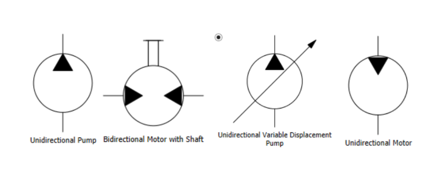
Pumps and Motors
Rotary devices are almost always represented by circles. The distinction lies in the direction of the energy.
- Hydraulic Pumps: A pump converts mechanical energy into hydraulic energy. In a diagram, this is a circle with a triangular arrow pointing outwards. This indicates the fluid is being pushed out into the system. If the arrow is solid black, it signifies a hydraulic pump; an open outline would indicate a pneumatic pump.
- Hydraulic Motors: A motor performs the inverse operation, converting hydraulic pressure back into mechanical rotation. Consequently, its symbol is a circle with the triangular arrow pointing inwards, showing that the fluid pressure is entering the component to drive it.
Cylinders
Cylinders are perhaps the most intuitive symbols to read because they visually resemble the physical component. They are depicted as a rectangle (the barrel) with a T-shaped element inside (the piston and rod).
- Single-Acting Cylinders: These have a fluid port on only one side of the piston. The return stroke is often achieved by an external force (like gravity on a dump truck bed) or an internal spring.
- Double-Acting Cylinders: These feature ports on both sides of the piston, indicating that hydraulic fluid power drives the rod in both extension and retraction.
.png)
Valves
Valves direct, restrict, or stop the flow of fluid. They are the decision-makers of the circuit.
- Directional Control Valves: These are typically represented by a series of connected squares. Each square represents a specific "position" the valve can take (e.g., neutral, forward, reverse). Arrows inside the squares show the path fluid takes in that specific position.
- Pressure Control Valves: These are often single squares containing an arrow. A pilot line (dashed line) will show how the valve senses pressure to open or close. A common example is a Pressure Relief Valve, which is normally closed but opens to dump fluid to the tank if pressure exceeds a safety limit.
.png)
Types of Lines
Just as roads on a map vary from highways to side streets, the lines in a hydraulic schematic vary to indicate their purpose.
- Main Flow Lines: These are solid, continuous, bold lines. They represent the primary pipes, hoses, or tubes carrying the high-pressure fluid that does the actual work of moving cylinders or spinning motors.
- Pilot Lines: These are drawn as dashed or dotted lines. Think of these as "signal" wires. They carry fluid, but not to do heavy lifting. Instead, they transmit pressure signals to open valves, actuate gauges, or provide feedback to pumps.
- Drain Lines: Also dashed (though sometimes with a specific pattern depending on the standard), these lines carry leakage oil or control fluid back to the reservoir at low pressure.
- Enclosure Lines: A line made of long dashes and dots often indicates a component enclosure. This tells you that all the symbols inside that box are physically contained within a single manifold or housing.
.png)
Reading Complete Diagrams
Reading a full hydraulic diagram is a process of tracing the flow of energy. A helpful strategy is to start at the power source (the pump) and follow the main flow line.
- Start at the Reservoir: Every system begins with fluid storage, usually represented by an open-top box symbol at the bottom of the page.
- Follow the Pump: Trace the line up to the pump symbol. Note if it is a fixed or variable displacement pump (indicated by a diagonal arrow through the circle).
- Check the Controls: Follow the flow from the pump to the directional control valve. Is it an open center or closed center system? The arrows inside the valve symbol in the neutral position will tell you if fluid flows back to the tank or is blocked when the machine is idle.
- End at the Actuator: Finally, trace the lines to the cylinders or motors. This confirms what physical action results from the valve's movement. And remember, you’ll want to trace the full loop. What happens on the return to tank is just as relevant as the trip out to the actuator.
.png)
Troubleshooting with Schematics
The true value of reading schematics becomes apparent when equipment fails. Without a diagram, troubleshooting is often a game of guesswork. With a schematic, you can use logic to isolate the issue.
For example, if a cylinder is drifting (moving when it shouldn't), you can look at the schematic to see what is supposed to hold it in place. Is there a check valve? A counterbalance valve? The symbol will tell you exactly where the locking mechanism is located. If the diagram shows a pilot-operated check valve, you know to check that specific component for debris or seal failure, rather than replacing the entire cylinder. This targeted approach saves time and money, getting your fleet back in operation faster.
While standard symbols cover the vast majority of hydraulic systems, the specific needs of modern transportation, construction, and agricultural equipment often require specialized configurations. Off-the-shelf components do not always fit the unique space or performance constraints of a customized machine.
This is where the abstraction of symbols meets the reality of engineering. You might design a circuit on paper using standard ISO symbols, but realizing that circuit might require a custom manifold block to fit a tight chassis, or a bespoke cylinder to handle specific load requirements.
At Bailey International, we bridge the gap between theoretical design and physical application. Our engineering team can look at a schematic, or help you create one, and develop custom hydraulic solutions that integrate seamlessly with your existing operations. Whether you need to combine multiple valve functions into a single, compact manifold or require a cylinder with unique mounting geometry, we ensure the physical product matches the logical intent of your design.

How to Read Hydraulic Schematics
For equipment manufacturers, your machinery is your reputation. Every component you select needs to withstand the rigors of tough environments, from dusty construction sites to high-pressure wash-downs. When it comes to electronic controls, one of the most critical specifications is the Ingress Protection (IP) rating.
What is an IP Rating?
Defined by international standards, such as IEC 60529 and ISO 20653, IP ratings classify the degree of protection an electrical enclosure provides against the intrusion of foreign objects (like dust and debris) and moisture (from drips, sprays, and submersion).
The rating consists of two digits:
- First Digit (Solids): Ranges from 0 (no protection) to 6 (completely dust-tight).
- Second Digit (Liquids): Ranges from 0 (no protection) to 8, with an additional 9K rating for high-pressure, high-temperature washdown applications.
Imagine a telehandler operating in a dusty quarry, or a boom lift working through a sudden downpour. If the electronic controls are not properly sealed, dust and moisture can penetrate the housing, leading to:
- Corrosion of internal components.
- Short circuits and electrical failure.
- Inaccurate or unresponsive controls.
These failures result in immediate operational downtime, costly field repairs, and damage to your reputation. Choosing a control with a low or unspecified IP rating is a risk that can have significant financial and operational consequences.
At Bailey, we understand that your equipment needs to perform flawlessly in the toughest environments. That’s why our products are designed and rigorously tested to meet some of the highest IP ratings in the industry. This commitment to quality ensures that when you integrate our controls, you are building in reliability from the start.
Let's look at a few examples from our product lineup:
Endurance Series Joystick: IP69K Protection
The Endurance Series is built for the most extreme applications. Its IP69K rating signifies that it is not only completely dust-tight but can also withstand powerful, high-temperature water jets. This makes it ideal for equipment exposed to frequent high-pressure washdown, such as municipal, agricultural, and mobile industrial applications. This level of protection ensures that no matter how harsh the cleaning protocol, the joystick's performance remains uncompromised.
Elevate and Harvest Series Joysticks: IP67 Sealing
Developed for scissor lifts and MEWPs, and agricultural machinery, the Elevate and Harvest Series both feature robust IP67 rated electronics. For an operator in the field, this means a sudden rainstorm or extremely dusty conditions won't lead to equipment failure.
Demand and Precision Series: IP67 Reliability
Similarly, our Demand Series for waste collection vehicles and Precision Series for telehandlers are fully sealed to IP67. These industries demand fade-free performance and intuitive control, day in and day out. The high IP rating ensures that dirt, grime, and moisture associated with these applications do not affect the internal electronics, providing consistent and reliable operation.
Beyond the Rating: A Commitment to Durability
While a high IP rating is a critical benchmark, it is part of a broader commitment to building durable and reliable products. For our Sure Grip Controls products, our designs incorporate:
- High-Quality Materials: We use high-impact polymers and robust components that resist chemical, salt, and UV degradation.
- Rigorous Testing: Our controls undergo extensive testing for EMC immunity, temperature tolerance (-40°C to 85°C), and operational longevity, often rated for over 20 million operations.
- Product Architecture: Many of our controls are designed with multiple layers of protection: primary sealing through enclosures, gaskets, or boots, with secondary protection via potted electronics. Designed to maintain sealing integrity over millions of cycles under real-world operating conditions.
Don’t let environmental factors dictate your equipment's reliability. Build with confidence by integrating controls engineered to endure.
Explore our full range of high-performance electronic controls and find the right solution for your next project.
.png)
What is an IP Rating for Heavy Equipment Controls?
One of the most destructive yet preventable issues is dieseling in hydraulic systems. This phenomenon, often triggered by something as simple as using the wrong fluid, can bring your machinery to a grinding halt. The solution starts with a fundamental practice: correctly labeling your fluid tanks.
Understanding the Dieseling Effect
Dieseling, also known as the "diesel effect," is a damaging event that occurs within a hydraulic system. It happens when air or other gas bubbles mix with hydraulic fluid and are rapidly compressed. This compression generates intense heat, causing the air-and-fluid mixture to ignite—much like fuel in a diesel engine. The hydraulic cylinder essentially becomes a combustion chamber, leading to micro-explosions that can wreak havoc on your equipment.
The Causes of Dieseling
Dieseling isn't a random event; it's the result of specific system vulnerabilities. The primary trigger is air entering the hydraulic system. Common causes include:
- Air Leaks: Worn or faulty seals, loose fittings, and damaged hoses are common culprits that allow air to be drawn into the system.
- Not Allowing Returned Oil Time to De-gas: To address this, ensure the reservoir is sized at a 3:1 ratio of tank capacity to pump GPM. Additionally, always return the oil below the fluid level to prevent splashing and promote optimal system performance.
- Rapid Compression: Abrupt or high-speed cylinder movements can compress trapped air too quickly, generating the heat needed for ignition.
- Low Fluid Levels: When the hydraulic fluid level is too low, the pump can draw in air from the reservoir.
- Improper Purging: Failing to properly bleed the system of air after maintenance or commissioning leaves it vulnerable.
- Incompatible Fluids: Mixing different types of hydraulic fluids, or using one not specified for the system, can increase the likelihood of dieseling.
The Damaging Effects of Dieseling
The consequences of dieseling extend far beyond a momentary bang or knock. These micro-explosions create a chain reaction of damage that compromises the entire system.
- Seal and Component Damage: The intense heat generated by dieseling can cause seals to burn, harden, and crack. This leads to leaks, which allows more contaminants to enter the system. The explosive pressure can also erode or damage metallic components like valves and pumps.
- Reduced System Efficiency: A system affected by dieseling often becomes sluggish and unresponsive. The internal damage and fluid degradation prevent actuators from moving smoothly, hindering performance.
- Increased Maintenance and Downtime: Frequent dieseling events necessitate costly repairs and component replacements. The unplanned downtime can disrupt operations and lead to significant financial losses.
- Fluid Degradation: The combustion process ages the hydraulic oil rapidly, diminishing its lubricating properties. You might notice the fluid turning dark or black, contaminated with soot-like particles from the explosions.
Why Proper Tank Labeling Is Non-Negotiable
It's easy to see how fluid contamination is a major risk factor for dieseling. One of the most common—and entirely avoidable—causes of contamination is fluid misidentification. When an operator tops off a hydraulic tank with the wrong fluid because of a missing or incorrect label, the system's integrity is immediately compromised.
Mixing incompatible fluids can lower the fluid’s flash point or introduce properties that promote aeration, creating the perfect conditions for dieseling. The financial and operational impacts are severe. A single mistake can lead to thousands of dollars in repairs, weeks of downtime, and a cascade of operational delays. Clear, consistent labeling is a small investment that protects against these monumental losses.
Best Practices for Labeling Hydraulic Tanks
Implementing a robust labeling system is a straightforward process that pays dividends in equipment reliability and safety.
- Use Clear and Durable Labels: Labels should clearly state the fluid type, grade, and any relevant specifications (e.g., ISO VG 46 Hydraulic Oil). They must be durable enough to withstand harsh environmental conditions without fading or peeling.
- Implement Color-Coding: Assign specific colors to different fluid types. For example, use blue for hydraulic fluid, red for transmission fluid, and yellow for diesel fuel. This provides an immediate visual cue that helps prevent cross-contamination.
- Label All Fill Points: Place labels not only on the main tank but also on all fill ports and any transfer containers used for topping off fluids.
- Train Your Personnel: A labeling system is only effective if your team understands and follows it. Train all operators and maintenance staff to recognize the labels, understand the color-coding system, and adhere strictly to the procedures.
Proactive Strategies to Prevent Dieseling
While labeling is a critical first step, a comprehensive prevention strategy involves regular maintenance and operational diligence.
- Regular System Inspections: Routinely check for leaks in hoses, fittings, and seals. Tighten loose connections and replace worn components at the first sign of wear.
- Proper Bleeding Procedures: Always bleed the hydraulic system to purge trapped air after maintenance or when commissioning new equipment. This involves stroking the cylinders through their full range of motion without load to force out any air bubbles.
- Use High-Quality, Compatible Fluids: Select the correct hydraulic fluid as specified by the equipment manufacturer. Using high-quality fluids with anti-foaming agents can significantly reduce the risk of aeration.
- Monitor Fluid Levels and Conditions: Regularly check the fluid level in the reservoir to ensure it is adequate. Monitor the fluid for signs of degradation, such as a dark color or burnt smell, which can indicate dieseling has occurred.
- Avoid Abrupt Movements: Operate equipment smoothly, avoiding sudden, jerky movements that cause rapid compression.
Preventing dieseling requires a proactive approach that combines proper fluid management with diligent system maintenance. Clear labeling of mobile equipment tanks is the simplest yet most effective measure you can take to prevent catastrophic fluid contamination and the destructive dieseling that follows. By establishing and enforcing these best practices, you protect your valuable equipment, ensure operational efficiency, and safeguard your bottom line.
At Bailey International, we are more than just a hydraulic components supplier—we’re your trusted partner in growth. For half a century, we have specialized in providing high-quality hydraulic components, including cylinders, valves, and custom solutions, to help businesses like yours operate safely and efficiently. Our experts are ready to help you select the right components and design a system built for optimal performance.
Don't Let Dieseling Destroy Your Hydraulic Systems
Hydraulic filters are the primary defense against contamination, ensuring your system operates with precision, power, and longevity.
Understanding how to properly maintain and replace these filters is critical. Neglecting them can lead to decreased efficiency, accelerated wear on expensive components, and even catastrophic system failure. This guide offers a clear, step-by-step approach to hydraulic filter replacement, explaining the "what," "why," and "how" of this essential maintenance task. By the end, you'll have the knowledge needed to protect your investment and keep your equipment running at peak performance.
The Role of Hydraulic Filters
At its core, a hydraulic system relies on clean fluid to transfer power. However, this fluid can become contaminated with particles from internal wear (like metal shavings) or external sources (like dust and dirt). If left unchecked, these contaminants act like sandpaper, grinding away at the sensitive internal components of pumps, valves, and cylinders. This leads to reduced efficiency, as contaminated fluid loses its protective properties and requires more pressure to do the same amount of work.
Hydraulic filters are engineered to capture these harmful particles, keeping the fluid clean and the system healthy.
Types of Hydraulic Filters
Hydraulic systems use several types of filters, each strategically placed to protect different parts of the circuit. While they all serve the same purpose of removing contaminants, their specific location and design are tailored to the pressures and flow conditions of that area.
- Suction Filters
Located between the fluid reservoir and the pump, suction filters (or strainers) provide the first line of defense. Their main job is to prevent large particles from entering the pump, which is often the most expensive and sensitive component in the system. They are typically low-pressure filters made of wire mesh.
- Pressure Filters
Installed downstream from the pump, pressure filters protect critical components like control valves and actuators from contaminants generated by the pump or that may have bypassed the suction filter. These are high-pressure filters designed to withstand the full operating pressure of the system, which can range from 1,885 to over 6,500 psi.
- Return Filters
Positioned in the return line, these filters clean the hydraulic fluid as it flows back into the reservoir. The return filter is often considered the most important filter in the entire system. It captures any debris generated during equipment operation, such as wear particles from cylinders and motors, before it can be recirculated. By cleaning the fluid just before it enters the tank, it ensures the entire reservoir remains as clean as possible.
- In-Tank and Breather Filters
In-tank filters are a space-saving design where the filter element is submerged inside the hydraulic reservoir, often serving the return line. Breather filters are located on the reservoir's vent, preventing airborne contaminants like dust and moisture from being drawn into the system as the fluid level changes.
How to Replace a Spin-On Hydraulic Filter
Spin-on filters are one of the most common designs and are relatively straightforward to replace. Following a careful process is key to avoiding fluid loss and ensuring a proper seal.
Here is a step-by-step guide:
1. Prepare Your Workspace
Before you begin, ensure the machine is parked on a level surface and the hydraulic system is turned off and depressurized. Place a suitably sized oil pan directly beneath the hydraulic filter to catch any fluid that will leak during removal.
2. Remove the Old Filter
Using a filter wrench, turn the existing filter counter-clockwise until it loosens. Once it's loose, you can typically finish unscrewing it by hand. Remove it slowly and carefully, keeping it upright to minimize spillage as you lower it into the oil pan.
3. Clean the Filter Head
With the old filter removed, use a clean, lint-free cloth to wipe down the filter head (the surface where the filter seals against the housing). Remove any old hydraulic fluid, dirt, or remnants of the old gasket. A clean surface is essential for a leak-free seal.
4. Prepare the New Gasket
Your new filter will come with a new gasket or O-ring. Before installation, lightly lubricate this new seal by applying a thin film of clean hydraulic fluid to its surface. This helps ensure it seats correctly and creates a tight seal without pinching or tearing.
5. Install the New Filter
Carefully screw the new filter onto the filter head by hand, turning it clockwise. Hand-tighten it until the gasket makes firm contact with the filter head. Then, using the filter wrench, tighten it an additional one-half to three-quarters of a turn, or as specified by the manufacturer. Be careful not to overtighten, as this can damage the filter or its seal.
After installation, run the machine and check for any leaks around the new filter.
Over time, filters become clogged with contaminants. A clogged filter can restrict fluid flow, forcing the system to work harder and generate excess heat.
Most pressure and return filters are equipped with a bypass valve as a failsafe. If the filter becomes too clogged, this valve opens to allow fluid to flow around the filter element, preventing the system from being starved of oil. However, when the bypass is open, contaminated, unfiltered fluid circulates through the system, accelerating wear and defeating the purpose of the filter.
Best Practices for Filter Maintenance
- Follow Manufacturer Recommendations: Your equipment manual is the best source for recommended replacement intervals. A general guideline is to change filters every time you change the hydraulic fluid, typically every 1,000 to 2,000 operating hours.
- Consider Operating Conditions: If your machinery operates in dusty or dirty environments, you will need to replace filters more frequently.
- Conduct Regular Inspections: Visually inspect your filters for signs of damage or deformities. Also, monitor filter pressure gauges if your system has them. A steady increase in pressure indicates the filter is becoming clogged.
- Use the Right Filter: Always replace filters with new ones that meet the manufacturer's specifications for pressure and efficiency ratings. Choosing a cheaper, lower-quality filter can compromise protection.
- Store Spares Properly: Keep spare filters in a clean, dry place to prevent them from becoming contaminated before you even install them.
Maintaining a hydraulic system is about more than just following steps; it’s about understanding the principles of fluid power and having a partner you can trust. A well-maintained system is a direct reflection of the quality of its components and the expertise behind its care.
At Bailey, we have 50 years of experience providing high-quality hydraulic components and expert support. From pumps and cylinders to the crucial filters that protect them, our extensive range of products ensures your system operates at its best. Our team of engineers and customer service experts is dedicated to providing guidance every step of the way, from component selection to maintenance best practices.
Power your progress with a partner committed to reliability and innovation. Browse our digital catalog or contact us today to see how Bailey can support your hydraulic system needs.
Hydraulic Filter Replacement Guide
When equipment operators notice their hydraulic cylinders drifting out of sync or failing to extend evenly, the culprit is usually a misunderstood component: the rephasing cylinder system. These specialized hydraulic systems play a critical role in maintaining synchronized movement across multiple cylinders, ensuring equipment operates smoothly and safely.
Whether you're managing a construction fleet, agricultural equipment, or forestry machinery, proper knowledge of these systems can save thousands in repairs and lost productivity.
How Rephasing Cylinders Work
A rephasing cylinder system enables multiple hydraulic cylinders to extend and retract in near-perfect unison, creating synchronized movement across an entire hydraulic lift system. The key to this synchronization lies in the rephasing passageway.
Located at the position of full extension, this passageway allows a small amount of hydraulic fluid to bypass the cylinder piston when fully extended. This bypass mechanism is what enables the cylinders to "rephase" or resynchronize themselves during operation.
When hydraulic fluid is applied to the cylinders, they extend together. However, over time, factors like internal leakage, air ingestion, or varying loads can cause the cylinders to fall out of sync. The rephasing passageway corrects this by allowing fluid transfer between cylinders at full extension, bringing them back into alignment.
This design eliminates the need for complex mechanical connections or additional flow control devices, making rephasing cylinders an elegant solution for applications requiring synchronized movement across multiple lifting points.
Advantages of Rephasing Cylinders
Rephasing cylinder systems offer several compelling benefits that make them ideal for mobile hydraulic applications:
- Enhanced System Stability: By maintaining synchronized movement, rephasing cylinders provide superior load distribution and equipment stability. This is particularly crucial for applications like agricultural implements or construction equipment where uneven lifting can cause damage or safety hazards.
- Simplified Design Requirements: Unlike traditional synchronized systems that require mechanical connections or complex flow dividers, rephasing cylinders achieve synchronization through their internal design. This eliminates additional components that could fail or require maintenance.
- No Parasitic Power Loss: Traditional flow divider systems often experience constant power losses due to pressure drops across flow control devices. Rephasing cylinders avoid this inefficiency, providing better overall system performance.
- Improved Operational Control: The ability to self-synchronize gives operators better control over complex hydraulic systems, reducing the skill level required for effective operation while improving overall equipment performance.
- Cost-Effective Implementation: While initial costs may be higher than single-cylinder systems, rephasing cylinders often prove more economical when considering the eliminated need for additional synchronization hardware and reduced maintenance requirements.
Disadvantages of Rephasing Cylinders
Despite their advantages, rephasing cylinder systems do present certain challenges that operators should be aware of:
- Increased System Complexity: Rephasing systems are inherently more complex than single-cylinder applications, requiring a deeper understanding of hydraulic principles for effective troubleshooting and maintenance.
- Higher Initial Investment: The specialized design and manufacturing requirements of rephasing cylinders typically result in higher upfront costs compared to standard hydraulic cylinders.
- Maintenance Requirements: The increased complexity translates to more sophisticated maintenance needs, often requiring technicians with specialized knowledge of rephasing system operation.
- Potential for Fluid Leakage: The rephasing passageways, while essential for operation, create additional points where internal leakage can occur, potentially affecting long-term system performance.
- Lack of Inherent Position Control: Rephasing systems excel at maintaining relative synchronization but don't provide absolute position control, which may be required for certain precision applications.
Rephasing cylinder systems operate using a master-slave configuration that ensures coordinated movement across multiple cylinders. Understanding this relationship is essential for proper system design and troubleshooting.
- Master Cylinder Function: The master cylinder receives hydraulic fluid directly from the system's pump and initiates movement for the entire system. It sets the pace and pressure for all connected cylinders, acting as the primary control point for the rephasing system.
- Slave Cylinder Operation: Slave cylinders receive hydraulic fluid through interconnected lines from the master cylinder. They follow the master cylinder's movement patterns, extending and retracting in response to pressure changes initiated by the master cylinder.
- Series vs Parallel Systems: Rephasing cylinders can be configured in either series or parallel arrangements. Series systems feature different bore and rod sizes across cylinders, while parallel systems use identical cylinder specifications. Series configurations are more common in applications requiring different load capacities across lifting points.
The master-slave relationship makes sure that all cylinders in the system respond uniformly to control inputs, maintaining synchronized movement even under varying load conditions. This configuration also simplifies the hydraulic circuit design by requiring only one primary control valve for the entire system.
Common Issues with Rephasing Cylinder Systems
Rephasing cylinder systems can exhibit several characteristic problems that operators should recognize and understand:
- Cylinder Creep (Drift): One of the most common issues, creep occurs when cylinders gradually move from their set position without operator input. This typically indicates air entrainment in the system or internal seal leakage. If multiple cylinders drift or the system feels "spongy," air is likely the primary culprit.
- Synchronization Failure: When cylinders fail to extend or retract at the same rate, the system has lost its synchronization. This can result from internal leakage, contaminated fluid, or worn seals that affect the rephasing passageway operation.
- Cylinder Bypass: A systematic issue where hydraulic fluid bypasses cylinder pistons inappropriately, causing erratic movement or complete loss of function. This requires methodical diagnosis to identify whether the problem lies with seals, contamination, or mechanical damage.
- Contamination Damage: Scoring of cylinder barrels and piston seals usually indicates that contaminants have entered the system. This can compromise the rephasing passageways and lead to complete system failure if not addressed promptly.
- Air Entrainment: Air trapped in the hydraulic system creates compressibility that interferes with precise cylinder movement and can cause the entire system to behave unpredictably.
Rephasing a Cylinder System
Proper rephasing procedures are essential for maintaining system performance and should be performed regularly as part of preventive maintenance:
Standard Rephasing Procedure: With the cylinder system fully extended, actuate the cylinder valve for 30 seconds. For systems that are rephased frequently, 5-10 seconds may be sufficient. This procedure allows excess air to be purged from the system while permitting fluid transfer through the rephasing passageways.
New System Considerations: New rephasing circuits often require extended rephasing sequences—sometimes several minutes—to bleed excessive air from the system. This process may need to be repeated multiple times until the system achieves proper synchronization.
Diagnostic Rephasing: Before performing maintenance rephasing, check cylinder rod positions by:
- Fully extending all cylinders, then retracting approximately 2 inches from the rephasing position
- Disconnecting all hydraulics from the machinery
- Measuring each extended cylinder rod length
- Allowing the equipment to stand for an extended period
- Remeasuring the rods to identify any drift
- Comparing measurements to identify problematic cylinders
This diagnostic approach helps pinpoint specific cylinders that may require individual attention or repair.
Best Practices for Maintaining Rephasing Cylinder Systems
Effective maintenance of rephasing cylinder systems requires a proactive approach that addresses both routine care and system-specific needs:
- Regular Rephasing Schedules: Establish routine rephasing intervals based on equipment usage patterns. High-use equipment may require weekly rephasing, while seasonal equipment might need rephasing at the beginning of each operating period.
- Fluid Quality Management: Maintain clean hydraulic fluid through regular filtration and replacement schedules. Contaminated fluid is one of the leading causes of rephasing system failure, making fluid quality management critical for long-term reliability.
- System Pressure Monitoring: Regularly check and maintain proper system pressure settings. Incorrect pressure can affect rephasing passageway operation and lead to synchronization problems.
- Environmental Considerations: Protect rephasing cylinder systems from environmental contaminants by maintaining proper seals and covers. Dust, dirt, and moisture can severely compromise system performance.
- Documentation and Record Keeping: Maintain detailed records of rephasing procedures, fluid changes, and system performance. This documentation helps identify patterns that may indicate developing problems before they cause equipment failure.
- Professional Inspection: Schedule regular professional inspections of rephasing cylinder systems, particularly for critical applications. Trained technicians can identify potential issues that may not be apparent during routine operation.
Maximizing Your Rephasing Cylinder Performance
Rephasing cylinders represent a solution for applications requiring synchronized hydraulic movement. While they require more technical understanding than simple cylinder systems, their benefits in terms of performance, reliability, and operational efficiency make them invaluable for many mobile hydraulic applications.
Success with rephasing cylinder systems comes from understanding their operation, recognizing common issues early, and maintaining consistent preventive maintenance practices. When properly maintained and operated, these systems provide the reliable, synchronized movement that keeps mobile hydraulic equipment operating at peak efficiency.
For more on this subject, be sure to check out our YouTube video on Rephasing Tie-Rod Cylinders!
Rephasing Cylinders: A Complete Guide for Mobile Hydraulics
Understanding how to correctly precharge hydraulic accumulators is all about ensuring your equipment operates at maximum efficiency while protecting your investment. Whether you're maintaining a fleet of construction vehicles or managing hydraulic systems in agricultural machinery, this comprehensive guide will walk you through everything you need to know about accumulator precharging.
The consequences of improper precharge extend far beyond immediate performance issues. Incorrect procedures can lead to bladder damage, reduced system capacity, and even complete system failure. By mastering these techniques, you'll not only improve equipment reliability but also extend the lifespan of your entire hydraulic system.
Understanding Hydraulic Accumulators
A hydraulic accumulator functions as the energy storage device of your hydraulic system, much like a battery stores electrical energy. These pressure vessels contain a membrane, bladder, or piston that separates and compresses an inert gas (typically nitrogen) from hydraulic fluid.
The core principle is elegantly simple: when system pressure increases, hydraulic fluid enters the accumulator and compresses the gas. When pressure drops or additional flow is needed, the compressed gas pushes the stored fluid back into the system. This mechanism allows accumulators to supplement pump flow, maintain consistent pressure, absorb shock, and provide emergency power when primary pumps fail.
Types of Hydraulic Accumulators
Three main types dominate the market, each with distinct characteristics:
- Bladder Accumulators use a flexible rubber bladder to separate gas and fluid. They're ideal for applications requiring rapid response and can handle high cycling rates effectively.
- Piston Accumulators employ a sliding piston as the separator. These units excel in high-pressure applications and offer excellent gas-tight sealing over extended periods.
- Diaphragm Accumulators utilize a flexible diaphragm for separation. They're typically used in smaller systems where space constraints matter most.
Each type requires specific precharge considerations, but the fundamental principles remain consistent across all designs.
Why Proper Precharge Matters
Accumulator precharge is the initial, static pressure of inert gas, like nitrogen, that is pumped into a hydraulic accumulator before it is connected to a hydraulic system. This precharge pressure allows the accumulator to store and release hydraulic fluid effectively by providing a baseline for the gas to be compressed against. Maintaining correct precharge pressure is essential for optimal hydraulic system performance. The benefits extend throughout your entire operation, creating a cascade of positive effects that impact everything from energy consumption to equipment longevity.
Performance Benefits
Proper precharge enhances system efficiency by ensuring the accumulator responds appropriately to pressure fluctuations. When precharge is set correctly, typically around 90% of system pressure, the accumulator maintains sufficient oil volume while preserving adequate gas space for effective pressure regulation.
This optimal balance means your system experiences fewer pressure spikes, reduced pump cycling, and more consistent performance across varying load conditions. The result is smoother operation, reduced energy consumption, and improved overall system responsiveness.
Cost Implications
The financial impact of proper precharge extends far beyond initial setup costs. Correctly precharged accumulators reduce wear on pumps, pipes, and other system components by minimizing pressure fluctuations and hydraulic shock. This translates directly into lower maintenance costs and extended component life.
Additionally, proper precharge reduces energy consumption by allowing pumps to operate more efficiently. When accumulators function correctly, pumps don't have to work as hard to maintain system pressure, resulting in measurable energy savings over time.
Risk Prevention
Incorrect precharge creates serious operational risks that can cascade throughout your hydraulic system. When precharge is too low, the accumulator's gas volume becomes insufficient, causing dramatic pressure drops during operation. This condition forces pumps to work harder and can lead to system instability.
Conversely, precharge pressure higher than system pressure prevents oil from entering the accumulator entirely. This scenario eliminates the accumulator's beneficial effects and can cause severe pressure fluctuations that damage sensitive components.
Perhaps most critically, bladder damage often results from improper precharge. When pressure relationships are incorrect, bladders can be forced against the accumulator shell or poppet valve, causing tears or permanent deformation that require costly replacement.
Step-by-Step Precharge Procedure
Safety must be your first priority when precharging hydraulic accumulators. These devices store significant energy that can cause serious injury if mishandled. Never attempt precharge procedures on a pressurized system, and always ensure complete depressurization before beginning work.
Essential Safety Precautions
Begin every precharge procedure by completely depressurizing the hydraulic system. This step is non-negotiable—accumulators store energy that can remain dangerous even after pumps are shut down. Install proper isolation valves and drain procedures to ensure safe working conditions.
Wear appropriate personal protective equipment, including safety glasses and protective clothing. Hydraulic fluid under pressure can cause serious injury, and nitrogen gas poses asphyxiation risks in confined spaces. Always work in well-ventilated areas and follow established safety protocols.
Arrange drainage systems to handle accumulator discharge safely. Never work on any circuit containing an accumulator until you're absolutely certain it's depressurized. This precaution protects both personnel and equipment from potentially catastrophic energy release.
Required Tools and Materials
Successful precharge requires specific equipment designed for hydraulic accumulator service. You'll need a nitrogen gas source—never use oxygen or other gases, as they can create explosive conditions when mixed with hydraulic fluids.
Your charging kit should include a pressure gauge accurate enough for your system requirements, proper fittings for your accumulator type, and bleed valves for pressure release. Ensure all connections are compatible with your specific accumulator model and rated for working pressures involved.
Store nitrogen cylinders upright and properly secured to prevent accidental tipping. When not in use, keep valves closed, fittings disconnected, and protective caps in place. These simple storage practices prevent accidents and reduce gas waste.
Detailed Precharge Steps
Start by setting the protective cap aside safely to prevent loss or damage. Install the charge kit's nitrogen fitting into the tank port before loosening the tank valve—this sequence prevents gas escape and ensures proper connection.
Once the fitting is tightened with a wrench, double-check all hose connections, fittings, and valves on the charge assembly. Most charge kits have bleed valves that must be tight before charging begins. The final connection will be the gas chuck to the accumulator valve, which should be tight but not over-torqued.
With all lines and fittings secure, open the gas chuck valve if your kit includes one. If precharge already exists in the accumulator, the pressure reading will display on the charge head's gauge immediately.
Open the nitrogen valve slowly. As long as tank pressure exceeds accumulator pressure, precharge will rise steadily. Monitor the gauge carefully and close both nitrogen and gas chuck valves when designated pressure is reached.
Note that gauge pressure often reads higher while the nitrogen tank valve remains open. To confirm precharge accuracy, re-open the gas chuck valve to display actual precharge pressure, which may be lower than initially observed. This phenomenon, called hysteresis, is normal and should be accounted for in your procedure.
Fill the accumulator slightly higher than target pressure to compensate for hysteresis effects. Be aware that simply measuring precharge pressure in small accumulators can lower the actual precharge pressure due to gauge volume effects.
Once precharge is set and confirmed, double-check that all valves are closed before removing the accumulator from the charge hose. Remove the charging hose from the tank and confirm once again that the valve is shut before replacing the protective cap.
Troubleshooting Common Precharge Issues
Even with careful procedures, precharge problems can occur. Understanding how to identify and resolve these issues quickly minimizes downtime and prevents secondary damage to your hydraulic system.
Identifying Precharge Problems
Pressure loss represents the most common precharge issue. If your accumulator loses pressure rapidly after charging, inspect all connections for leaks and examine the bladder or piston seals for damage. Gradual pressure loss over days or weeks is normal, but significant drops within hours indicate problems requiring immediate attention.
Erratic system behavior often signals precharge issues. If your hydraulic system experiences unexpected pressure fluctuations, inconsistent response, or unusual pump cycling, check accumulator precharge as part of your diagnostic routine.
Visual inspection can reveal external problems, but internal issues require pressure testing to diagnose properly. Use appropriate gauges and testing procedures to evaluate precharge retention and system integration.
Common Solutions
For rapid pressure loss, systematically check all fittings and connections. Tighten loose fittings and replace damaged seals as needed. If problems persist, the bladder or piston seals may require replacement—a job best performed by qualified technicians.
Gradual pressure loss may indicate normal permeation through bladder materials or minor seal weepage. Monitor loss rates carefully and establish regular recharge intervals based on your system's specific performance characteristics.
When precharge problems recur frequently, examine system operating conditions for causes. Excessive cycling, temperature extremes, or contamination can accelerate accumulator wear and create recurring precharge issues.
When to Seek Professional Help
Some accumulator problems require specialized knowledge and equipment beyond typical maintenance capabilities. If you encounter bladder replacement needs, internal component damage, or complex system integration issues, consult with hydraulic specialists who have appropriate tools and experience.
Persistent problems that resist standard troubleshooting procedures often indicate underlying system issues that extend beyond simple precharge adjustment. Professional diagnosis can identify root causes and prevent recurring failures.
Maintenance Best Practices
Establishing regular maintenance routines protects your investment and ensures consistent system performance. Proactive accumulator care prevents most common problems and extends equipment life significantly.
Regular Inspection Schedule
Check accumulator precharge pressure when first installed and at least once daily for the first week of operation. If no noticeable pressure loss occurs during this period, extend checking intervals to weekly, then to every three to six months for established systems.
Create maintenance logs that track precharge pressure over time. This data helps identify gradual changes that might indicate developing problems before they cause system failures.
Monitor system performance indicators that relate to accumulator function. Changes in pump cycling frequency, pressure stability, or response characteristics can signal accumulator issues before pressure measurements reveal problems.
Preventive Maintenance
Install proper isolation valves and drainage systems that facilitate safe accumulator maintenance. These systems pay for themselves by reducing maintenance time and improving safety during service procedures.
Maintain clean hydraulic fluid and effective filtration systems. Contamination accelerates accumulator wear and can cause premature failure of seals and bladders. Regular fluid analysis helps identify contamination sources before they damage components.
Temperature control protects accumulator components from excessive thermal stress. Extreme temperatures accelerate seal degradation and can cause bladder materials to become brittle or excessively soft.
Long-term Performance Optimization
Document accumulator performance characteristics when systems are new and operating properly. This baseline data becomes invaluable for troubleshooting future problems and optimizing maintenance intervals.
Train maintenance personnel on proper precharge procedures and safety requirements. Consistent, knowledgeable service prevents most accumulator problems and ensures safe working conditions.
Consider upgrading older systems with improved accumulator designs or enhanced monitoring capabilities. Modern accumulators often offer better performance and longer service life than older units.
Maximizing Your Hydraulic System Investment
The techniques outlined in this guide provide the foundation for reliable, efficient operation that protects your equipment investment while maximizing productivity.
Remember that accumulator precharge affects every aspect of your hydraulic system's performance. From pump efficiency to component longevity, proper precharge creates positive effects that cascade throughout your operation. The time invested in mastering these procedures pays dividends through reduced downtime, lower energy costs, and extended equipment life.
Regular monitoring and maintenance transform accumulator care from reactive repairs to proactive optimization. By implementing the inspection schedules and maintenance practices described here, you'll prevent most common problems while identifying developing issues before they cause system failures.
The safety procedures outlined in this guide aren't optional recommendations—they're essential requirements for protecting personnel and equipment. Never compromise on safety when working with hydraulic accumulators, as the stored energy involved can cause serious injury or equipment damage if mishandled.
For complex systems or persistent problems, don't hesitate to consult with hydraulic specialists who have the expertise and equipment to address challenging issues. Professional support can prevent costly mistakes and ensure your systems receive the specialized care they require.
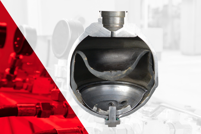
The Complete Hydraulic Accumulator Precharge Guide
A counterbalance valve is a critical component in many hydraulic systems, especially those dealing with suspended loads. Its primary job is to hold cylinders in place and manage over-running loads safely, preventing them from dropping uncontrollably. If you've ever wondered whether you can fine-tune one of these valves yourself out in the field, you're not alone. While it might seem like a straightforward adjustment, it's a task that comes with significant risks.
Understanding the Counterbalance Valve
At its core, a counterbalance valve is a type of load control valve. It maintains pressure in a portion of a hydraulic circuit to counteract the force of a load, like the weight held by a cylinder on a front-end loader. Without it, gravity could cause the load to drift down or drop suddenly when the directional control valve is centered or shifted.
How Does It Work?
To understand its function, let's look at a typical cylinder application.
- Holding the Load: When no pressure is applied to lift or lower the load, the counterbalance valve remains closed, trapping hydraulic fluid in the rod-end of the cylinder. This creates a back-pressure that holds the load securely in position.
- Lowering the Load: To lower the load, hydraulic pressure is sent to the other side of the cylinder (the cap end). This pressure acts on a pilot line connected to the counterbalance valve. Pilot pressure works on a larger surface area inside the valve—often at a 3:1 or 4:1 ratio—which helps push the valve's spool open against the load-induced pressure and its internal spring. As the valve opens, fluid can exit the rod end, allowing the cylinder to retract and the load to lower smoothly.
- Built-in Safety: If the load starts to drop too fast, the pressure in the pilot line will decrease. This causes the counterbalance valve's spool to partially close, restricting the flow of fluid and slowing the load's descent. This self-regulating feature is so effective at controlling over-running loads.
Is It Just a Pilot-Operated Check Valve?
While they share some similarities, a counterbalance valve is not the same as a pilot-operated check valve. A pilot-operated check valve can hold a load, but it cannot control its movement if it starts to run away. It simply opens or closes. A counterbalance valve, on the other hand, modulates the flow of fluid to ensure the load moves at a controlled speed. For any application where an uncontrolled load drop is possible, a counterbalance valve is the correct and safer choice.
The Risks of Field Adjustments
Adjusting a counterbalance valve in the field is a difficult task, even for seasoned technicians. The interaction between the pilot assist, the actuator, and the load itself makes finding the correct setting a delicate balancing act. Once the valve is installed and properly set at the factory or in a controlled workshop environment, its adjustment screw should be treated primarily as a manual override, not a routine tuning knob.
Incorrectly adjusting the valve can lead to serious problems:
- Load Drifting: If the pressure setting is too low, the valve may not seal tightly, allowing the load to slowly drift downward. A failed or improperly set valve often sticks in the open position, leading to this exact issue.
- System Instability: If the setting is too high, the valve may require excessive pilot pressure to open, causing jerky or erratic movement. This instability can strain the entire hydraulic system and create unsafe operating conditions.
- Contamination Issues: Adjusting the valve in a dusty field environment increases the risk of introducing contaminants. Debris can cause the internal check valve or spool to stick open, leading to valve failure and load drift.
When You Might Consider a Field Adjustment
There are rare circumstances where a field adjustment might be inevitable, such as when a valve is replaced without the means for a proper bench setup. If you must proceed, it is critical to do so with extreme caution and a clear understanding of the procedure.
Precautions to Take Before You Start
First and foremost: safety is non-negotiable.
- Secure the Load: Lower the load completely to the ground or secure it with mechanical locks. Never work on the hydraulic system with a suspended load.
- Relieve Pressure: Ensure all hydraulic pressure in the system has been blown down to zero.
- Read the Manual: Always consult the valve manufacturer’s instructions, as adjustment procedures can vary.
A Cautious Adjustment Procedure
If adjustment is necessary, follow these general steps carefully:
- Set to Max Pressure: Begin by adjusting the valve's spring to its highest setting. On many valves, this is done by turning the adjustment screw counterclockwise. This ensures the valve will hold the load initially.
- Raise the Load: Start the machine and carefully raise the load a short distance off the ground.
- Induce a Slow Drift: With the area completely clear of people and anything of value, slowly turn the adjustment screw clockwise to gradually lower the pressure setting. Continue until the load begins to drift downward very slowly.
- Find the Sweet Spot: Once a slow drift begins, immediately turn the adjustment screw back in the opposite direction (counterclockwise) just until the drifting stops.
- Add a Safety Margin: From that point, turn the adjustment screw another quarter-turn in the same direction (counterclockwise) to add a small safety margin to the pressure setting.
- Lock it Down: Tighten the lock nut to secure the adjustment screw, being careful not to alter the setting.
Cycle the machine a few times to ensure the load moves smoothly and holds securely without drifting.
Partner with the Experts for Reliable Performance
While understanding the mechanics of a counterbalance valve is valuable, setting one correctly is a task best left to professionals with the right tools and environment. An improperly adjusted valve isn't just an inconvenience; it's a significant safety hazard.
At Bailey International, we have five decades of expertise in providing high-quality hydraulic components and custom solutions. Our engineering teams can help you select and configure the right components for your needs, ensuring they are set up for optimal safety and performance from day one. Whether you need a single valve for a DIY project or a complete, customized hydraulic system, we provide expert guidance every step of the way.
Don't leave safety to chance. Contact our team today to explore our selection of hydraulic components and get the expert support you need for your next project.

Can You Adjust a Counterbalance Valve in the Field?
Recognizing the warning signs of hydraulic system failure is the same as protecting your investment, maintaining operational efficiency, and ensuring workplace safety. The cost of emergency repairs, production downtime, and potential safety hazards far exceeds the expense of a system replacement.
Many operators mistakenly treat hydraulic issues as isolated incidents, addressing symptoms rather than underlying systemic problems. This reactive approach often leads to cascading failures, where one compromised component places additional strain on the entire system. Knowing when your hydraulic system has reached the end of its useful life empowers you to make informed decisions about replacement timing and budgeting.
The following warning signs indicate that your hydraulic system may need comprehensive replacement, rather than continued patchwork repairs. Each sign reflects deeper issues that, when combined, paint a clear picture of a system operating beyond its optimal performance parameters.
- Reduced System Performance
When hydraulic systems begin to falter, reduced performance typically appears as the first noticeable symptom. This manifests as decreased operating speeds, reduced lifting capacity, or sluggish response times during operation. Your equipment may struggle to complete tasks that were once effortless, requiring multiple attempts or extended cycle times.
Performance degradation occurs gradually, making it easy to overlook until productivity suffers significantly. Operators often compensate by pushing equipment harder or accepting longer completion times, masking the underlying issue. However, this reduction in performance indicates that critical components—pumps, cylinders, and/or valves—are no longer operating within their design specifications.
The impact on productivity extends beyond individual machine performance. When hydraulic systems operate inefficiently, entire workflows slow down, affecting project timelines and operational costs. Equipment that once handled demanding tasks with precision may now require careful operation to avoid stalling or failure mid-cycle.
- Unusual Noises
A well-functioning hydraulic system operates with characteristic sounds—the steady hum of pumps and the controlled movement of actuators. When unusual noises emerge, they serve as audible warnings of internal problems developing within the system.
Whining sounds often indicate pump cavitation, where insufficient hydraulic fluid creates air bubbles that collapse violently within the system. Grinding noises typically signal excessive wear between moving components, suggesting contamination or inadequate lubrication has compromised internal surfaces. Knocking or hammering sounds may indicate pressure spikes or loose components that could lead to catastrophic failure.
These acoustic signatures provide valuable diagnostic information about component condition and system health. Experienced operators learn to distinguish between normal operational sounds and warning signs, but any persistent change in noise levels warrants immediate investigation. Ignoring these auditory warnings often leads to component failure and expensive emergency repairs.
- Leaking Fluid
Hydraulic fluid leaks represent both environmental hazards and clear indicators of system compromise. Even small leaks signal that seals, gaskets, or component housings have degraded beyond their design limits. As systems age, multiple leak points often develop simultaneously, creating ongoing maintenance challenges and safety concerns.
Identifying leak sources requires systematic inspection of all hydraulic connections, cylinder seals, pump housings, and valve bodies. External leaks are readily visible, but internal leakage within components can be more challenging to detect. Internal leaks reduce system efficiency and pressure capabilities, while increasing heat generation throughout the system.
The severity of leaks varies from minor seepage to significant fluid loss that affects system performance. However, any persistent leaking indicates that critical sealing components have exceeded their service life. Continued operation with multiple leak points often accelerates system degradation as contamination enters through compromised seals and fluid levels drop below optimal operating parameters.
- Overheating
Hydraulic systems generate heat during normal operation, but excessive temperatures indicate serious underlying problems. Overheating occurs when heat generation exceeds the system's cooling capacity, often resulting from increased internal friction, contaminated fluid, or inadequate heat dissipation.
Temperature monitoring reveals system health trends over time. Gradual temperature increases suggest progressive component wear, while sudden temperature spikes may indicate component failure or system blockages. High temperatures accelerate fluid degradation, reduce seal life, and increase wear rates throughout the system.
Heat exchangers and cooling systems play crucial roles in maintaining optimal operating temperatures. When these components become fouled or fail, the entire hydraulic system suffers. Proper reservoir sizing allows for adequate heat dissipation, but oversized or undersized reservoirs can contribute to temperature management problems.
- Contaminated Fluid
Hydraulic fluid serves as both the power transmission medium and the primary lubricant for system components. Contaminated fluid loses its protective properties and introduces abrasive particles that accelerate wear throughout the system. Common contaminants include dirt, metal particles, water, and chemical breakdown products from degraded fluid.
Regular fluid analysis provides objective measurement of contamination levels and fluid condition. Clean fluid appears transparent with consistent color, while contaminated fluid may appear cloudy, discolored, or contain visible particles. Water contamination often creates a milky appearance, while metal particles indicate ongoing wear within system components.
Filtration systems remove contaminants during operation, but filters have finite capacity and effectiveness. When contamination levels exceed filtration capabilities, the entire system suffers accelerated wear. Contaminated fluid also reduces system efficiency, requiring higher pressures to achieve the same work output and generating additional heat throughout the system.
- Frequent Breakdowns
Repeated component failures indicate systemic problems that extend beyond individual part replacement. When hydraulic systems require frequent repairs, the underlying causes often involve multiple compromised components, inadequate maintenance, or operation beyond design parameters.
Each breakdown creates additional stress on remaining components, accelerating overall system degradation. Emergency repairs typically focus on immediate functionality rather than long-term reliability, creating cycles of recurring problems. The cumulative cost of frequent repairs, replacement parts, and operational downtime often exceeds the investment required for complete system replacement.
Root cause analysis reveals whether breakdowns stem from normal wear, operational abuse, or design inadequacies. Addressing symptoms without correcting underlying causes perpetuates the breakdown cycle and increases total ownership costs. Frequent failures also indicate that system reliability has dropped below acceptable levels for certain applications.
- Increased Energy Consumption
Inefficient hydraulic systems require more energy to produce the same work output, resulting in higher operating costs and missed sustainability targets. Energy consumption increases occur gradually as components wear and system efficiency degrades over time.
Monitoring energy usage patterns reveals system health trends and identifies when efficiency drops below acceptable levels. Newer hydraulic technologies offer significantly improved energy efficiency compared to older systems, making replacement financially attractive through reduced operating costs.
Component wear, internal leakage, and contaminated fluid all contribute to reduced efficiency. Pumps work harder to maintain system pressure, motors consume more power, and heat generation increases throughout the system. These efficiency losses compound over time, making older systems increasingly expensive to operate.
- Visible Wear and Tear
External inspection reveals obvious signs of system aging and component degradation. Hoses show cracking, bulging, or surface deterioration that indicates approaching failure. Cylinder rods display scoring, pitting, or corrosion that compromises seal effectiveness and allows contamination entry.
Mounting points, brackets, and structural components may show signs of fatigue, loosening, or deformation from repeated stress cycles. Paint deterioration, rust formation, and component discoloration provide visual evidence of environmental exposure and aging processes.
Proactive replacement of worn components prevents catastrophic failures, but extensive wear throughout multiple system elements suggests that comprehensive replacement offers better long-term value. Visual inspection combined with performance monitoring provides a complete picture of system condition and remaining service life.
- Outdated Technology
Technology advancement in hydraulic systems continues at a rapid pace, with modern systems offering improved efficiency, better controls, enhanced safety features, and superior diagnostics capabilities. Older systems may lack these beneficial features, operating with outdated technology that limits performance and increases maintenance requirements.
Modern hydraulic systems incorporate electronic controls, pressure monitoring, temperature management, and diagnostic capabilities that weren't available in earlier generations. These features improve operational efficiency, reduce maintenance costs, and provide early warning of developing problems.
Upgrading to current technology often provides immediate benefits in performance, reliability, and operating costs. While older systems may continue functioning, they cannot match the capabilities and efficiency of modern hydraulic technology. The productivity gains and reduced maintenance requirements of newer systems often justify replacement costs through improved operational economics.
- Exceeding Service Life
Every hydraulic system has design parameters that specify expected service intervals and total operational life. Operating systems beyond these recommendations increases failure risk and reduces reliability for critical applications.
Manufacturers provide service life guidelines based on testing, field experience, and component capabilities. These recommendations account for normal wear patterns, maintenance intervals, and expected operating conditions. Exceeding service life doesn't guarantee immediate failure but significantly increases the probability of unexpected breakdowns.
Planned replacement based on service life recommendations allows for proper budgeting, scheduling, and system selection. This proactive approach minimizes operational disruptions and ensures optimal system performance throughout the equipment's working life. Running systems beyond recommended service intervals often results in catastrophic failures that require emergency replacement at higher costs.
Making the Right Decision for Your Operation
Learning to recognize these warning signs equips you to make informed decisions about hydraulic system replacement timing and investment. Multiple warning signs appearing simultaneously can indicate that comprehensive system replacement offers better value than continued repairs and component replacement.
Regular system assessment, including performance monitoring, fluid analysis, and visual inspection, provides the data needed for informed replacement decisions. Working with experienced hydraulic system specialists ensures that replacement systems meet current operational requirements while incorporating beneficial technological improvements.
The transition from reactive maintenance to planned replacement strategies reduces total ownership costs, improves operational reliability, and enhances workplace safety. When your hydraulic system displays multiple warning signs, replacement investment pays dividends through improved productivity, reduced downtime, and lower long-term operating costs.
Top 10 Signs It's Time to Replace Your Hydraulic System
Whether you manage a construction fleet, maintain agricultural equipment, or run a repair shop, selecting the right pump is crucial.
The challenge lies in understanding what hydraulic pumps do and determining which type best fits your specific application, operating conditions, and performance requirements.
Key Considerations for Choosing a Hydraulic Pump
Before diving into specific pump types, establish the fundamental requirements of your hydraulic system. These core considerations will guide your selection and ensure compatibility with existing equipment.
Flow Rate Requirements
Flow rate, measured in gallons per minute (GPM) or liters per minute (LPM), determines how quickly your hydraulic system operates. Calculate the maximum fluid volume needed when all system components operate simultaneously. For example, if your excavator powers the boom, arm, and bucket cylinders simultaneously, your pump must deliver sufficient flow for all three functions.
Consider both current needs and potential future expansion. Undersizing the flow rate leads to sluggish performance, while oversizing wastes energy and increases operational costs.
Pressure Requirements
System pressure requirements vary dramatically across applications. A basic lift system might operate effectively at 1,500 PSI, while heavy-duty construction equipment may require 3,000 PSI or higher. Review your equipment specifications and operating manuals to determine the maximum working pressure your system will encounter.
Remember that pressure requirements can change based on load conditions. A forestry harvester on steep terrain will have different pressure demands than the same equipment on flat ground.
Fluid Compatibility
Not all hydraulic pumps work with every type of hydraulic fluid. Some pumps excel with conventional petroleum-based fluids, while others are designed for biodegradable or fire-resistant alternatives. Check your fluid specifications against pump compatibility charts, paying attention to viscosity ranges, temperature stability, and chemical composition.
Fluid compatibility affects pump operation, seal life, wear rates, and maintenance intervals. Using incompatible fluids can void warranties and lead to premature failure.
Efficiency Considerations
Pump efficiency directly impacts operating costs through energy consumption and heat generation. Modern hydraulic pumps offer both volumetric efficiency (actual fluid moved versus theoretical capacity) and mechanical efficiency (how effectively mechanical power converts to hydraulic power).
Higher efficiency pumps reduce fuel consumption in mobile applications and lower electricity costs in stationary systems. They also generate less heat, reducing cooling requirements and extending component life.
Types of Hydraulic Pumps
Understanding the characteristics of different pump types helps match the right technology to your specific application requirements. Each pump design offers distinct advantages and limitations.
Gear Pumps
Gear pumps represent the most straightforward hydraulic pump design, using intermeshing gears to move fluid from inlet to outlet. Their simplicity offers several practical advantages for many applications.
These pumps excel in low to medium-pressure applications, typically operating up to 2,500 PSI. Their robust construction handles contaminated fluids better than more complex designs, making them ideal where perfect fluid cleanliness is difficult to maintain.
Gear pumps offer excellent reliability and are relatively inexpensive to purchase and maintain. Replacement parts are widely available, and most technicians can service them without specialized training. However, they produce more noise and have limited pressure capability compared to other pump types.
Vane Pumps
Vane pumps use sliding vanes in a rotor to create chambers that expand and contract as the rotor turns. This design provides smooth, pulse-free fluid flow required by many applications.
The smooth operation of vane pumps makes them well-suited for medium-pressure systems where flow consistency matters. They operate more quietly than gear pumps and offer good efficiency across their operating range. Many mobile hydraulic systems use vane pumps for functions requiring steady, controlled movement.
Vane pumps require cleaner fluid than gear pumps, as contamination can damage the sliding vanes and cam ring surfaces. They also have more components than gear pumps, potentially increasing maintenance requirements.
Piston Pumps
Piston pumps deliver the highest pressure capability and efficiency among hydraulic pump types. They use reciprocating pistons to generate flow, with several design variations available.
Radial Piston Pumps
Radial piston pumps arrange pistons in a radial pattern around a central cam. They excel in high-pressure, low-flow applications and offer exceptional durability. These pumps often serve in industrial presses, injection molding machines, and other applications requiring precise pressure control.
Axial Piston Pumps
Axial piston pumps align pistons parallel to the drive shaft, using a swash plate or bent axis design to create reciprocating motion. They provide efficient operation across a wide range of pressures and flows, making them popular in construction equipment, agricultural machinery, and industrial systems.
Many axial piston pumps offer variable displacement, allowing flow adjustment without changing engine speed. This feature enables significant energy savings in applications with varying load requirements.
Servo Pumps
Servo pumps combine the high-pressure capability of piston pumps with precise electronic control. They respond quickly to command signals, making them ideal for applications requiring accurate positioning or force control.
These sophisticated pumps integrate seamlessly with modern control systems, enabling advanced functions like load sensing, pressure compensation, and programmable response characteristics. However, they require more complex installation and maintenance.
Factors Affecting Pump Selection
Beyond basic pump types, several application-specific factors influence the selection process. These considerations ensure your chosen pump performs reliably in your specific operating environment.
Media Type Considerations
The characteristics of your hydraulic fluid significantly impact pump selection and performance. Viscosity affects how easily the pump moves fluid—thicker fluids require more power and may limit maximum operating speed. Temperature variations change fluid viscosity, potentially affecting pump performance across seasonal temperature swings.
Chemical composition matters for seal compatibility and corrosion resistance. Some fluids contain additives that can affect certain pump materials, while others may require pumps designed for aggressive chemicals.
Contamination levels in your system also influence pump choice. While gear pumps tolerate some contamination, precision pumps like servo units require extremely clean fluid to prevent damage.
Environmental Conditions
The operating environment affects pump selection in several ways. Extreme temperatures require pumps designed for thermal expansion and contraction, while high-vibration environments need robust mounting and internal construction.
Consider maintenance accessibility in your environment. Pumps installed in confined spaces or harsh conditions benefit from designs that minimize service requirements.
Suction and Discharge Head
Suction head represents the pump's ability to draw fluid from the reservoir, while discharge head indicates the pressure it can generate. These specifications must match your system's requirements for reliable operation.
Inadequate suction capability leads to cavitation—bubble formation that damages pump components and reduces efficiency. Ensure your pump can handle the vertical lift from reservoir to pump inlet, plus any restrictions in the suction line.
Discharge head requirements depend on your system's maximum operating pressure plus any additional pressure needed to overcome line losses and elevation changes.
Custom Solutions for Specialized Applications
While standard hydraulic pumps serve many applications effectively, some operations benefit from custom electrohydraulic solutions tailored to specific requirements. These solutions optimize performance beyond what off-the-shelf components can achieve.
Custom solutions address unique combinations of flow, pressure, and control requirements that standard products cannot accommodate. They integrate multiple functions into single units, reducing complexity and improving reliability while optimizing space utilization.
Bailey International's engineering team collaborates with customers to develop custom solutions that address specific performance requirements. This partnership ensures the final product integrates seamlessly with existing systems while delivering optimized performance for the intended application.
Custom solutions also provide opportunities to incorporate the latest technology, including smart sensors, predictive maintenance capabilities, and advanced control algorithms that are not available in standard products.
Making Your Final Selection
Selecting the right hydraulic pump requires careful evaluation of your system requirements, operating conditions, and performance goals. Start by documenting your flow rate and pressure requirements, then identify any special conditions like extreme temperatures, contaminated fluids, or space limitations.
Consider the total cost of ownership, including initial purchase price, installation costs, energy consumption, and maintenance requirements. A more expensive pump with higher efficiency often provides lower long-term costs through reduced energy consumption and extended service life.
Evaluate your technical support requirements. Complex systems may benefit from working with suppliers who offer engineering assistance, custom modifications, and comprehensive technical support throughout the product lifecycle.
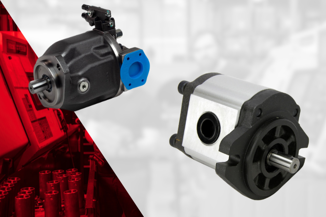
Choosing the Right Hydraulic Pump
Electrohydraulic solutions combine the precision of electronic control with the power of hydraulic systems, creating highly efficient components that power everything from construction equipment to industrial machinery. As original equipment manufacturers face increasing pressure to deliver superior performance while managing costs, these specialized systems have become essential for maintaining competitive advantage.
The challenge for OEMs isn't just finding hydraulic components—it's finding the right components that integrate seamlessly with existing systems while meeting strict quality standards and budget constraints. Generic, off-the-shelf solutions rarely deliver the performance optimization that custom applications demand.
The Strategic Advantages of Tailored Electrohydraulic Solutions
Increased Efficiency Through Precision Engineering
Custom electrohydraulic solutions are designed to meet specific application needs. Unlike off-the-shelf parts that require manufacturers to make compromises, these tailored systems provide the exact flow rates, pressure levels, and controls needed for performance..
This precision engineering translates directly to operational benefits. Equipment powered by custom-configured electrohydraulic systems typically operates 15-25% more efficiently than those using generic alternatives. The improved efficiency reduces energy consumption, minimizes heat generation, and extends component life cycles.
For OEMs, this means delivering equipment that performs better in the field while reducing warranty claims and maintenance requirements. The enhanced performance also provides a competitive differentiator when bidding for contracts or competing in price-sensitive markets.
Long-Term Cost Savings Through Strategic Customization
While tailored electrohydraulic solutions may require higher initial investment compared to off-the-shelf alternatives, the total cost of ownership typically decreases significantly over the equipment's operational life. Custom components eliminate the need for costly modifications, adapters, and workarounds that generic solutions often require.
The cost benefits extend beyond component pricing. Custom solutions reduce assembly time during manufacturing, minimize inventory complexity, and decrease the likelihood of field failures. These operational improvements directly impact production costs and profitability.
OEMs working with specialized electrohydraulic partners also benefit from consolidated sourcing arrangements. Rather than managing multiple suppliers for different components, manufacturers can streamline their supply chains while maintaining quality standards and delivery schedules.
Enhanced Reliability Through Application-Specific Design
Reliability represents a critical factor for OEMs, particularly those serving demanding industries like construction, mining, and industrial manufacturing. Custom electrohydraulic solutions address specific environmental conditions, duty cycles, and performance requirements that generic components may not withstand.
Application-specific design considers factors such as operating temperature ranges, contamination levels, vibration exposure, and maintenance access. Components engineered for these specific conditions demonstrate superior reliability and longer service life compared to generic alternatives.
This enhanced reliability reduces warranty costs, minimizes field service requirements, and strengthens customer relationships. OEMs can confidently specify longer warranty periods and reduce service network requirements when equipment incorporates properly engineered custom components.
Bailey International's Collaborative Approach to Custom Solutions
Partnership-Driven Design Process
Bailey International's approach to custom electrohydraulic solutions emphasizes collaborative engineering partnerships with OEMs. Rather than simply supplying components, Bailey's technical team works directly with manufacturers to understand application requirements, environmental conditions, and performance objectives.
This partnership approach begins during the design phase, where Bailey's engineers collaborate with OEM design teams to optimize component specifications and integration requirements. The collaborative process ensures that custom solutions integrate seamlessly with existing systems while meeting all performance and quality standards.
The partnership extends beyond initial design to include ongoing support throughout the product lifecycle. Bailey provides technical assistance for field applications, troubleshooting support, and component optimization recommendations based on real-world performance data.
Comprehensive Customization Capabilities
Beyond standard component configuration, Bailey offers complete system customization including cylinders, power units, and control systems engineered for specific applications. These comprehensive solutions address complex integration challenges that individual components cannot solve.
Custom Cylinders: Engineered solutions using high-grade materials and precise manufacturing processes to meet exact application requirements. Bailey's cylinder customization includes bore sizes, stroke lengths, mounting configurations, and seal selections optimized for specific operating conditions.
Power Units: Complete hydraulic power systems designed for seamless integration with OEM equipment. Customization options include pump selection, reservoir sizing, filtration systems, and control interfaces tailored to application requirements.
Control Systems: Application-specific control solutions powered by our Sure Grip Controls brand, providing precise system control. Custom control solutions integrate seamlessly with existing equipment architecture while providing enhanced functionality and reliability.
Real-World Applications and Success Stories
Heavy Equipment Simulation Training
CM Labs Simulations, a global leader in heavy equipment simulation training, required specialized electronic throttle components for their simulator systems. The standard Sure Grip Controls 10459 Floor Electronic Throttle provided the foundation, but needed specific modifications to meet their exacting requirements.
Bailey's technical team collaborated with CM Labs to modify the throttle component, addressing precise functional requirements while maintaining the reliability and performance standards essential for training applications. The customized solution integrated seamlessly with CM Labs' Edge Series simulators, enhancing performance and user experience.
This three-year partnership demonstrates how collaborative engineering approaches deliver superior results compared to standard component sourcing. The ongoing relationship has enabled continuous improvement and optimization based on real-world performance data.
Industrial Manufacturing Applications
Bailey serves diverse industrial applications, including oil and gas, marine, material handling, and manufacturing equipment. Each industry presents unique challenges requiring specialized solutions.
For oil and gas applications, Bailey provides components engineered for harsh environmental conditions, including extreme temperatures, corrosive environments, and high-vibration applications. Marine applications require components resistant to saltwater corrosion while maintaining precise control in challenging sea conditions.
Material handling equipment demands components that provide smooth, precise control for operator safety and productivity. Bailey's customized solutions address these specific requirements while maintaining the reliability essential for industrial applications.
Maximizing Value Through Strategic Partnerships
Technical Expertise and Support
Bailey's technical expertise extends beyond component manufacturing to include comprehensive engineering support throughout the product lifecycle. This support includes system design consultation, component selection optimization, and field application assistance.
The technical team provides training resources, including specialized sessions that help OEM teams understand component capabilities and optimization opportunities. This educational approach ensures that manufacturers can maximize the value of their custom electrohydraulic solutions.
Ongoing technical support includes troubleshooting assistance, performance optimization recommendations, and component upgrade paths as technology evolves. This comprehensive support approach strengthens the partnership relationship while ensuring long-term success.
Supply Chain Reliability and Flexibility
Bailey maintains extensive inventory and in-house manufacturing capacity to ensure reliable delivery schedules. This supply chain strength enables OEMs to maintain production schedules even when facing urgent requirements or unexpected demand changes.
The company's distribution network, including strategically located warehouses, provides rapid response capabilities for both standard and custom components. This logistics infrastructure supports OEMs' need for flexible, reliable supply chain partnerships.
Bailey's supply chain approach also includes demand forecasting and inventory optimization services that help OEMs reduce carrying costs while maintaining service levels. These value-added services demonstrate the comprehensive nature of Bailey's partnership approach.
Strategic Implementation for OEMs
Assessment and Planning
Successful implementation of tailored electrohydraulic solutions begins with comprehensive assessment of current applications, performance requirements, and cost objectives. OEMs should evaluate existing component performance, identify optimization opportunities, and establish clear success metrics.
The assessment process should include analysis of total cost of ownership, including initial component costs, installation requirements, maintenance needs, and expected service life. This comprehensive evaluation ensures that custom solutions deliver genuine value compared to alternatives.
Planning should also consider supply chain implications, including sourcing consolidation opportunities, inventory optimization, and logistics coordination. These strategic considerations maximize the benefits of custom electrohydraulic solutions.
Partner Selection and Collaboration
Choosing the right electrohydraulic solutions partner requires evaluation of technical capabilities, manufacturing capacity, and service approach. OEMs should prioritize partners with demonstrated experience in their specific industries and applications.
The collaborative relationship should begin during the evaluation phase, with potential partners providing technical consultation and preliminary design recommendations. This early collaboration helps establish the partnership foundation while ensuring alignment on technical requirements and expectations.
Ongoing collaboration includes regular performance reviews, optimization assessments, and strategic planning sessions. These partnership activities ensure continuous improvement and adaptation as requirements evolve.
Building Your Competitive Advantage
Tailored electrohydraulic solutions represent more than component customization—they provide strategic advantages that strengthen competitive positioning, reduce operational costs, and enhance customer satisfaction. OEMs that embrace custom solutions gain flexibility, reliability, and performance advantages that generic alternatives cannot match.
The key to success lies in establishing collaborative partnerships with experienced electrohydraulic solutions providers who understand your industry requirements and can deliver comprehensive support throughout the product lifecycle. These partnerships enable continuous improvement and innovation while ensuring reliable supply chain performance.
Bailey International's comprehensive approach to custom electrohydraulic solutions provides OEMs with the technical expertise, manufacturing capabilities, and partnership commitment necessary for long-term success. From rapid component customization through complete system engineering, Bailey delivers solutions that enhance equipment performance while reducing total cost of ownership.
Explore how tailored electrohydraulic solutions can benefit your team today.
Why Tailored Electrohydraulic Solutions Are Game-Changers for OEMs
For over 45 years, Bailey International has set the standard for engineering excellence in mobile hydraulics. As a trusted industry leader, Bailey designs and manufactures hydraulic power units that serve as the driving force behind the most demanding applications. Our unwavering commitment to quality and innovation ensures that every power unit delivers optimum performance, reliability, and durability.
The Foundation of Every Hydraulic System
A hydraulic power unit is the core of any hydraulic system—responsible for transforming fluid power into controlled, mechanical force. Bailey International’s units consistently deliver the precision and strength required by professionals in agriculture, transportation, construction, and manufacturing.
Each Bailey hydraulic power unit is engineered with three essential components:
- Motor: Initiates the system with dependable power and consistent rotation.
- Pump: Ensures reliable fluid movement and system efficiency.
- Valve: Provides precise control, directing hydraulic fluid exactly where needed.
Every Bailey hydraulic power unit is built to exacting standards, offering flexibility and superior performance across a vast range of configurations.
Tank
The tank is engineered to safely store hydraulic fluid, with capacities ranging from 0.5 gallons to over 1,000 gallons. Bailey offers meticulous sizing to meet your specific operational requirements.
Pump
Our pumps are designed for seamless operation inside the tank, providing optimal suction and maximizing system longevity. Each pump is selected to fit the unique flow and pressure needs of your application.
Valve Options
Bailey provides an extensive selection of valve types, each manufactured for superior control and robust service life. Our valves activate work ports that efficiently power cylinders, jacks, and steering mechanisms.
Motor
Bailey’s catalog includes a broad spectrum of motors to meet any need:
- DC Motors
- AC Motors
- Hydraulic Motors
Each motor is engineered to deliver efficient and reliable performance in your specific application. Our DC motors are designed for use in mobile and industrial equipment, with options for low voltage/high torque or high voltage/low speed applications. AC motors are available in both single and three phase options, suitable for a wide range of agricultural, construction, and material handling equipment. For heavy-duty machinery requiring precise control and smooth operation, our hydraulic motors offer superior performance.
Discover the perfect solution for your needs by contacting our team of experts to discuss your requirements or request a quote. Together, we can power the success of your next project!
Hydraulic Power Unit Basics
The fluid power industry, like many others, is facing challenges due to the recent global economic slowdown. For OEMs who rely on hydraulic components, this downturn emphasizes the need to adapt quickly to stay competitive, maintain profitability, and drive growth.
To help your business navigate the slowdown, we’ve outlined four key strategies to build resilience, boost efficiency, and position your company for long-term success.
Diversify Product Offerings for Market Longevity
Diversifying your product lineup has never been more important. Expanding your offerings can reduce risks from market fluctuations and help you stay competitive in evolving industries. Here’s how you can future-proof your business:
- Consider Adding Electronic Controls to Your Products: Integrating electronic controls into your product lineup is a smart way to keep up with the growing demand for electro-hydraulic systems in mobile markets. By offering high-efficiency control solutions like precision flow valves and customized controls, you can attract a wider customer base while staying ahead of the shift toward automation.
- Focus on Energy-Efficient Systems: Sustainability is a major focus for industries like agriculture and construction, which are under pressure to meet environmental goals. Energy-efficient solutions, such as high-efficiency hydraulic pumps, can help your business cater to these needs while positioning you as a leader in the green technology market.
By offering innovative solutions, you’ll tap into new market segments and reduce reliance on traditional products. Diversifying your product lineup ensures your business stays competitive, even as market demands change.
Enhance Customer Service to Cultivate Loyalty
Exceptional customer service is the key to building strong business relationships, especially during challenging times. Here are three proven strategies to improve customer retention and satisfaction:
- Provide Expert Technical Support: Help your customers get the most out of your products with tailored technical support. Equip your team with product training and updated technical guides, so they can quickly troubleshoot issues and optimize system performance. By offering personalized assistance, you add value to every interaction.
- Stay Proactive with Communication: Keep your customers informed by anticipating their needs. Send restocking notifications, reminders for maintenance contracts, or updates on new products and services. Proactive communication builds trust and creates a lasting partnership.
- Ensure Faster Turnaround Times: Reduce delays and improve customer satisfaction by streamlining your processes. Offer fast shipping options, such as 2-day delivery, to get your products to customers quickly and efficiently.
By focusing on technical expertise, proactive engagement, and fast service, your business establishes itself as a reliable partner. Prioritizing customer service not only improves retention, but also helps you stand out in a competitive market.
Upskill Your Workforce
A business downturn is the perfect time to focus on workforce development. By upskilling your employees, you can foster innovation, stay competitive, and adapt to changing market demands. Here are three key strategies to invest in your team:
- Cross-Training Programs: Cross-training employees enhances operational flexibility and promotes team collaboration. Cross-trained teams are better equipped to solve problems across departments, leading to faster decision-making and improved efficiency.
- Industry-Specific Certifications: Encourage your employees to earn certifications relevant to your industry. Certified staff can provide expert insights and tailored recommendations, improving customer satisfaction and building trust.
- Workshops on Emerging Technologies: Stay ahead of the curve by offering training in artificial intelligence (AI), machine learning, and the Internet of Things (IoT). Employees skilled in these technologies can create innovative solutions that meet evolving customer needs and market trends.
Upskilling your workforce is an investment in your business's future. Equip your team with the tools they need to succeed, and you’ll be ready to face any challenge.
Focus on Operational Efficiency
Reducing overhead costs without sacrificing quality is key to maximizing profit margins. To help you run your business more efficiently, here are two proven ways to streamline operations:
- Optimize Inventory Management: Use predictive inventory management software to keep your shelves stocked with best-selling items, while avoiding excess inventory of slow-moving products. This strategy minimizes waste and saves money, helping boost productivity and cut costs.
- Leverage Data-Driven Decision Making: Rely on real-time data from advanced ERP (enterprise resource planning) systems to monitor expenses, track performance metrics, and identify areas for improvement. By using data effectively, you can improve operational efficiency and reduce unnecessary business costs.
Implementing these strategies will help you increase profitability while maintaining high-quality operations.
Building a Resilient Future
Navigating changes in the fluid power market requires adaptability, innovation, and strategic planning. To stay ahead during a slowdown, businesses can focus on diversifying product lines, strengthening customer relationships, upskilling employees, and streamlining operations. These strategies not only help overcome challenges, but also prepare your business for strong growth when the market recovers.
At Bailey International, we are more than just a hydraulic components supplier—we’re your trusted partner in growth. We specialize in providing high-quality hydraulic components, custom hydraulic solutions, and expert support tailored to meet the unique needs of OEMs and businesses in the fluid power industry.
Whether you’re searching for durable hydraulic cylinders, hydraulic pumps, or custom engineering, our team is here to help you succeed. Let us support your profitability and adaptability in this ever-changing market.
Contact Bailey International today to explore reliable, cost-effective solutions that drive your business forward.

4 Ways to Combat Market Slowdown
A hydraulic system is a closed system that converts pressurized fluid to mechanical energy. Hydraulic fluid is moved by pumps through control valves and on to mechanical actuators like hydraulic cylinders or motors, which then use the pressure to move implements such as tractor buckets, excavators, and lift cranes.
Components of a Hydraulic System
A hydraulic system is composed of various components to keep the fluid under the desired pressure, clean, and moving in the right direction. Below is an overview of those components
Reservoir Tank
The hydraulic tank acts as a reservoir, holding fluid, and is connected directly to the pump. It allows air bubbles to dissipate and contamination particles to settle, as well as allows the oil to cool while it is not circulating. A vented filter cap controls air flow, and a filter or strainer keeps contaminants out of the hydraulic fluid.
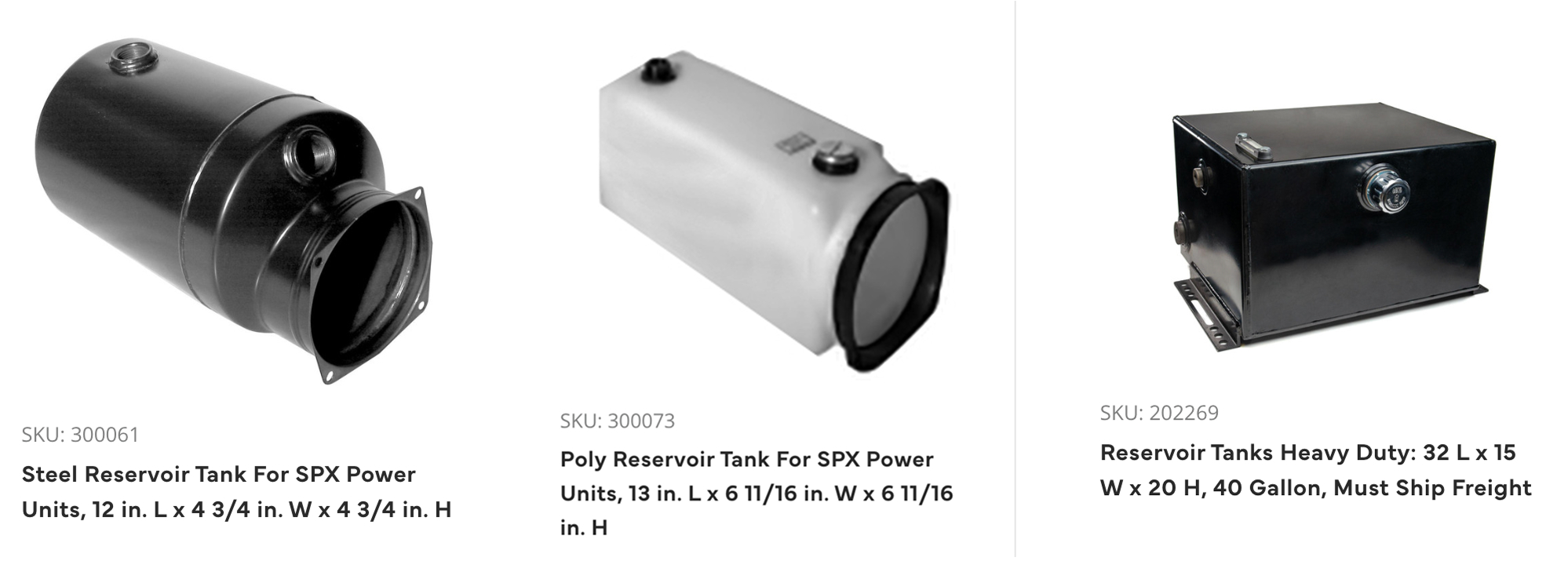
Pump and Engine
The hydraulic pump moves liquid from the reservoir tank through the system driven by an engine. Pump designs are typically two-stage, PTO or manual hydraulic, while the engine can be gas, diesel or electric depending on access to power, the horsepower needed and mounting style.
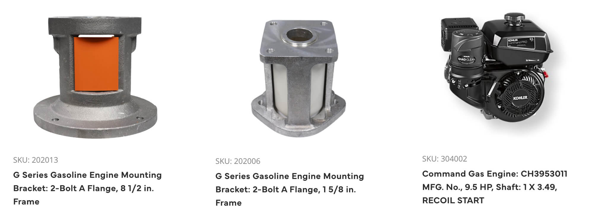
Pressure Gauges and Relief Valve
Once liquid is circulating, gauges can be used virtually anywhere in the system to monitor pressure. In addition, a relief valve controls the fluid pressure that powers the hydraulic cylinder; excess fluid is returned to the reservoir tank. This prevents pressure build-up and potential damage to equipment.
Valve Assembly
The hydraulic valve assembly controls the direction, pressure and flow rate of fluid through a hydraulic circuit. It regulates the speed of motors and movement of cylinders. Directional control valves are most common, controlling fluid flow from the pump to the cylinders and other system components.
Cylinder
A hydraulic cylinder is an actuator that creates linear movement by converting hydraulic energy back to a mechanical movement – so it is the component that drives the work performed by mobile equipment. Cylinders can be used to lift, push, pull and press loads that require exceptional force.
Motor
Similar to cylinders, motors are actuators that converts hydraulic pressure and flow into movement, but it’s converted into torque and angular displacement (rotation) rather than linear motion. The amount of pressure and displacement of a motor will determine how much torque is produced while the amount of flow will determine the speed.
Flow Control Valve
The purpose of a flow control valve is to regulate the flow rate to motors and cylinders, thereby regulating the speed of those components.
Fluid Cooler
This unit removes the excess heat generated from the hydraulic fluid and helps to keep the temperature within a limited range before returning to the reservoir. Without proper cooling, the hydraulic system could overheat, causing component damage. Keeping the system properly cooled also extends hydraulic fluid life.
.png)
How Does A Hydraulic System Work?
A hydraulic cylinder is made up of a steel barrel, a piston connected to a piston rod that moves back and forth, and mounting accessories. A cylinder creates linear movement by converting hydraulic energy back to a mechanical movement. They are used in equipment to lift, push, pull and press loads that require exceptional force.
Hydraulic cylinders can be double-acting (pressurized oil moves it in either direction) or single-acting (pressurized oil extends the rod in one direction, and gravity pushes it back to its natural position).
To properly select a cylinder there are several factors to consider:
- Bore size (tube diameter) which determines how much force can be delivered at a given oil pressure
- Stroke, or how far the rod extends
- Piston rod diameter which is critical since it must apply that force without bending or buckling
- Speed determines the gallons per minute needed from the hydraulic pump and determines the correct port sizes
- How the cylinder will mount
We have hydraulic formulas and hydraulic calculators to make sure your cylinder is sized properly for the application. We at Bailey International are your trusted source for hydraulic products, system design help, as well as education and general support. After the sale, it’s the service and support that count!a
What is a Hydraulic Cylinder?
There are different types of hydraulic cylinders available that are designed to work within specific applications. Below is a brief explanation of the most common cylinder types along with some specialty cylinders that are available from Bailey.
The Basics
A hydraulic cylinder is an actuator that creates linear movement by converting hydraulic energy back to a mechanical movement. Cylinders are made up of a steel barrel, a piston connected to a piston rod that moves back and forth, and mounting accessories. They are used in equipment to lift, push, pull and press loads that require exceptional force.
Available in several different body styles, including tie-rod, welded and telescopic, hydraulic cylinders can be single-acting or double-acting.
Single-acting cylinders vs double-acting cylinders
Single-acting Cylinders
In a single acting hydraulic cylinder, piston force is applied in a single direction when pressurized oil extends the rod. Once the oil is exhausted, gravity and the load return it to its natural position.
Double-acting Cylinders
Double-acting cylinders can exert force in two directions. The piston cylinder is divided into two pressurized chambers that enable the rod to achieve both outward and return strokes. Pressurized oil allows the rod to move in either direction.
So how do you choose between single-acting and double-acting? Single-acting cylinders are best for simpler applications, where you only need to push in one direction. Double-acting cylinders are more complex to operate and maintain but offer both push and pull forces, have more precise control, and are better for repetitive actions.
Basic Body Styles
Tie-Rod Cylinders
Tie-rod hydraulic cylinders use high strength threaded steel rods to hold the two end caps to the cylinder barrel. They are held together by four or more threaded tie bolts that run the length of the entire cylinder tube. These bolts hold the baseplate and head together. They usually have static seals to prevent leakage between the barrel and end-cap interface. Tie-rod cylinders are best for medium to light-duty mobile applications. Their cost of ownership is lower, since they are easier to assemble, maintain and repair.
Standard Tie-rod Cylinder
Rephasing Tie-rod Cylinder
Rephasing tie-rod cylinders incorporate an internal bypass for synchronizing the cylinder in a series circuit. They are ideal for construction and agricultural applications where you need to lift independent loads plumbed in series.
Welded Cylinders
In a welded hydraulic cylinder, the barrel is welded to the end caps rather than using steel rods. Static seals are used to seal the head or gland of a welded cylinder. Welded body cylinders have many advantages over tie-rod cylinders, including a compact design that usually can withstand higher pressures, often greater than 5,000 psi. Because of this, they are often used on mobile machinery where space is at a premium. Their rugged design not only makes them ideal for extreme weather and operating conditions, but also contributes to much longer service life than tie-rod cylinders because they do not fail due to tie-rod stretch at high pressures and long strokes.
Telescopic Hydraulic Cylinders
Telescopic cylinders are several individual cylinders (like the sections of a telescope) nested together in order of decreasing size. Because this style of cylinder is able to extend from its compact design, it provides an exceptionally long stroke. The collapsed length of a typical telescopic cylinder varies between 20% to 40% of its extended length. In general, telescopic cylinders are single acting and are available in two to five stages. They are frequently used in trucks in the construction industry, vehicle trailers, garbage and dump trucks, as well as in the agricultural industry.
Bailey Specialty Cylinders
Chief AT
The Chief® AT line of cylinders is a durable alternative to tie-rod cylinders for lighter duty construction and agriculture applications. Unlike a tie-rod, there are no bolts. They feature an easy snap ring on the rod-end gland for easy field repair.
Chief WX
The Chief® WX line of cylinders features patented designs and is ideal for applications where port adjustability and overall cylinder space is restricted. It features an adjustable 360° rotating gland with retaining ring design offering 2 base-end ports for applications requiring a variety port positions.
Chief WTG
The Chief® Welded Tang cylinder, or WTG for short, features Bailey's patented adjustable 360° rotating gland and is one of our most durable cylinders. It is sometimes referred to as a lug end cylinder, due to its one piece lug mount welded to both the rod and base ends. The WTG can utilize a spherical ball or steel bushing insert to improve wear life. Tang cylinders are commonly used in heavy duty construction equipment.
.png)
Types of Hydraulic Cylinders
Like any mechanical component, hydraulic pumps are prone to failure if not carefully maintained. With proper understanding and attention, you can not only prevent these failures but also extend the life of your hydraulic system significantly.
The Common Causes of Hydraulic Pump Failure
Despite their robust design, hydraulic pumps are vulnerable to specific challenges. Improper system maintenance or design issues can lead to one or more of the following problems:
1. Excess Heat
One of the most common culprits of hydraulic pump failure is heat. Hydraulic systems naturally generate heat during operation. While some heat is normal, too much can be detrimental. If left unaddressed, excess heat can cause significant damage to seals, valves, and other system components.
Why Is Heat an Issue?
High oil temperatures break down hydraulic fluids, reducing their viscosity and causing inadequate lubrication. Over time, this leads to increased wear and tear on the pump and other components. Additionally, heat can cause seals to harden or deteriorate, leading to oil leaks and eventual system failures.
How to Prevent Excess Heat
- Proper Reservoir Size: Ensure the oil reservoir is adequately sized for the system’s operating conditions. A well-sized reservoir allows for better heat dissipation.
- Install Oil Coolers: Adding an oil cooler to your system can help keep hydraulic fluid temperatures within acceptable levels.
- Monitor Fluid Levels Regularly: Insufficient oil levels can cause the system to overheat. Always maintain adequate oil levels and top off when necessary.
2. Contamination
Contamination within the hydraulic system is another leading cause of pump failure. This can occur when dirt, debris, or other foreign particles enter the system.
Why Is Contamination Dangerous?
Contaminants can damage the pump's internal components, such as pistons and gears, reducing efficiency and causing wear. They can also block vital system pathways, further straining the pump and other hydraulic components.
How to Prevent Contamination
- Regularly Change Filters: Use proper filtration systems and change filters at regular intervals to keep the hydraulic fluid clean.
- Use High-Quality Hydraulic Fluids: Poor-quality or incompatible hydraulic fluids can introduce foreign substances. Always use the recommended fluid type for your system.
- Inspect and Maintain Seals: Worn-out seals can allow contaminants to enter the system. Regular inspection and replacement of seals help prevent this issue.
3. Cavitation
Cavitation occurs when there is insufficient flow of hydraulic fluid to the pump’s inlet. This creates voids or air bubbles within the fluid, which collapse under pressure, damaging pump components.
Signs of Cavitation
One telltale sign of cavitation is foamy hydraulic oil. This indicates air is entering the system. Other symptoms include unusual noise during operation or a decrease in pump efficiency.
How to Prevent Cavitation
- Increase the Size of the Inlet Line: A larger inlet line can improve the flow of hydraulic fluid to the pump.
- Avoid Elbows and Bends: Remove any unnecessary elbows, bends, or filters on the inlet line to ensure a smoother flow of hydraulic oil.
- Position the Reservoir Above the Pump: Having the oil reservoir located above the pump helps maintain a steady flow and reduces the likelihood of cavitation.
Prolonging the Life of Your Hydraulic Pump
Preventing pump failure starts with proper system design and consistent maintenance practices. Here are additional tips to maximize the lifespan of your hydraulic pump:
- Monitor Oil Quality and Temperature: Regularly check the oil temperature and quality to detect early signs of heat-related issues or contamination.
- Schedule Routine Inspections: Periodically inspect the system components for wear, leaks, and signs of damage. Early detection can save you thousands in repairs and downtime.
- Implement Predictive Maintenance: Use advanced diagnostic tools to identify potential issues before they escalate. Many modern hydraulic systems now include sensors that monitor performance in real-time.
Partnering with a Reliable Source for Hydraulic Components
When it comes to maintaining and repairing hydraulic systems, the quality of your components matters. Low-quality parts not only wear out quickly but can also introduce new vulnerabilities to your system. That’s where trusted experts like Bailey International can make a difference.
With over 40 years of expertise in hydraulic components, Bailey International provides reliable, high-quality solutions tailored to your industry’s needs. From hydraulic pumps to filters, their extensive range of products and expert support ensures your system operates at its best.
Why Choose Bailey International?
- Experience You Can Trust: With decades of experience, Bailey has become a trusted partner for construction professionals, hydraulic engineers, and mechanics.
- Custom Solutions: For unique operational needs, Bailey offers customized components through its MVP program.
- Comprehensive Support: Bailey provides expert guidance every step of the way, from design to maintenance.
Looking to optimize your hydraulic systems even further? Take advantage of Bailey International’s vast catalog of hydraulic components and extensive expertise. Whether you need routine maintenance supplies or custom solutions, they’ve got you covered. Visit our digital catalog today and discover how Bailey can power your progress.
_thumbnail.jpg)
Why Hydraulic Pumps Fail (And How to Prevent It)
Hydraulic cylinders are a critical component in countless industries, from construction and oil & gas to agriculture and manufacturing. Among the most common types of hydraulic cylinders are tie rod cylinders and welded cylinders, both of which excel in different applications.
If you're looking to choose between the two, understanding their construction, advantages, and ideal use cases is essential. This guide breaks down the key differences between tie rod and welded cylinders, so you can make informed decisions for your operations.
What is a Tie Rod Cylinder?
A tie rod cylinder is a type of hydraulic cylinder held together using high-strength steel tie rods. The rods run the length of the cylinder, keeping the baseplate and gland secured.
Key Features of Tie Rod Cylinders:
- Easily Repairable
These cylinders are built to be disassembled efficiently, making them simple to repair and maintain in the field. With just a wrench, you can remove the tie rods, open the cylinder, and service its internal components.
- Compact Design for Specific Applications
Tie rod cylinders are generally found in applications where space is constrained and the cylinder size needs to remain standard.
Ideal Use Cases:
Tie rod cylinders are most commonly found in:
- Industrial machinery
- Food processing equipment
- Medical devices like hospital beds
If your operation involves controlled environments or predictable loads, tie rod cylinders often fit the bill perfectly.
What is a Welded Cylinder?
Unlike tie rod cylinders, a welded cylinder relies on a single, sealed construction. The end caps are welded directly to the body of the cylinder, eliminating the need for tie rods altogether.
Key Features of Welded Cylinders:
- Durable and Compact Design
Welded cylinders offer a sturdy and sleek design, which is particularly advantageous in demanding, high-pressure applications. They can endure higher stress and loads compared to tie rod cylinders.
- Requires Specialized Tools for Repairs
Repairing welded cylinders typically requires a vise grip and spanner wrench for gland removal. This makes fixing them slightly more technical than tie rod cylinders.
Ideal Use Cases:
Welded cylinders are designed for heavy-duty environments such as:
- Construction equipment (e.g., excavators, loaders)
- Farming machinery
- Oil & gas applications where rugged durability is essential
Their compact design and high reliability make them a preferred choice for mobile equipment.
Key Differences Between Tie Rod and Welded Cylinders
1. Construction
- Tie Rod Cylinders: Held together by external tie rods, making them easier to disassemble.
- Welded Cylinders: Features a seamless body with welded ends for added durability.
2. Maintenance and Repair
- Tie Rod Cylinders: Easier to repair in the field with basic tools.
- Welded Cylinders: Require more advanced tools and technical expertise for maintenance.
3. Durability
- Tie Rod Cylinders: Better suited for lower pressure and controlled applications.
- Welded Cylinders: Can endure higher pressure and are built to withstand more rugged environments.
4. Application Suitability
- Tie Rod Cylinders: Best for stationary, indoor applications with predictable conditions.
- Welded Cylinders: Ideal for mobile, heavy-duty operations with high performance demands.
5. Cost
- Tie Rod Cylinders: Tend to be more cost-effective and easier to replace due to simple construction.
- Welded Cylinders: Slightly more expensive upfront but offer long-term reliability for extreme conditions.
Which Cylinder Should You Choose?
The choice between a tie rod cylinder and a welded cylinder ultimately depends on your application and priorities. Here’s a quick comparison to help you decide:
- Tie Rod Cylinder: Tie rod cylinders are easy to maintain with basic tools. They are durable in controlled conditions and cost-effective, making them ideal for stationary, industrial applications.
- Welded Cylinder: Welded cylinders are more durable and designed for high-pressure, rugged environments. Maintenance requires specialized tools, and they have a higher upfront cost, making them perfect for mobile and heavy-duty applications.
If you're working in environments that require extensive field maintenance, like a factory floor, tie rod cylinders are your best bet. However, if your equipment operates in tough conditions—such as construction sites or oil fields—welded cylinders are designed to handle the pressure.
Why Choose Bailey for Your Hydraulic Cylinder Needs?
Bailey is a trusted leader with over four decades of expertise in hydraulics. Whether you're in construction, oil & gas, manufacturing, or agriculture, we provide top-quality hydraulic solutions you can rely on.
Here’s why professionals choose Bailey:
- Comprehensive Product Line: From tie rod cylinders to welded cylinders, we offer a wide range of standard and custom options.
- Expert Support: Need help finding the right cylinder for your application? Our engineering team is here to provide technical guidance.
- Reliable Delivery: With strategically located warehouses, we ship to most locations in just 2 days.
For more detailed specifications or to explore our hydraulic solutions, reach out to Bailey International today.
Not sure which cylinder suits your needs? Contact our team today to explore your options.
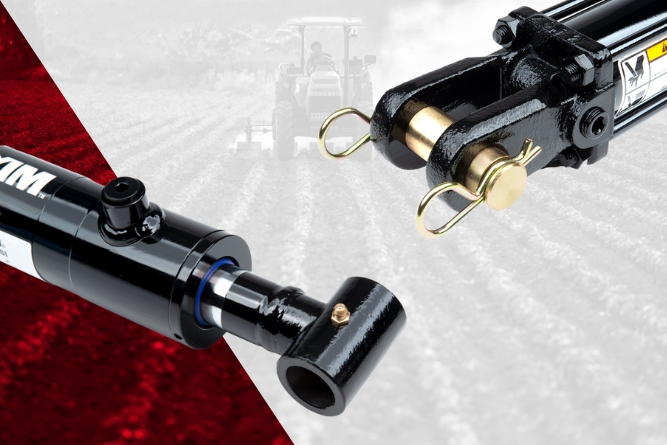
Tie Rod vs. Welded Cylinders: Which One is Right for Your Application?
What are custom manifolds, and how can they transform hydraulic systems? This blog post explores the role of custom manifolds in modern hydraulic applications, their benefits, and their importance to professionals like hydraulic engineers and construction specialists. Read on to learn more and discover how Bailey International's experts can help you optimize your systems.
What is a Hydraulic Manifold?
A hydraulic manifold provides pathways for the flow of hydraulic fluid within a system. It's a central component that distributes oil or fluid between pumps, actuators, cylinders, motors, and other parts. Instead of using multiple hoses or tubes, a manifold consolidates these pathways, ensuring seamless communication between components.
Manifolds can be simple in design, managing basic flow paths, or highly complex, controlling multiple operations simultaneously. The key to their performance is customization—tailoring the manifold to the specific needs of the system.
Simple Manifolds
A simple manifold, such as a relief manifold, connects basic elements of a hydraulic system. It features ports for pressure (P) and tank lines (T), and often houses a relief valve to manage pressure. For example, when system pressure exceeds a critical threshold, the relief valve opens, diverting excess fluid to prevent damage.
Complex Manifolds
Complex manifolds are engineered to execute more intricate functions, guiding hydraulic fluid through multiple pathways and managing multiple control valves. They enable systems to support advanced operations, such as running multiple actuators or pumps simultaneously.
Whether your system requires basic pressure management or intricate control across various components, custom manifolds simplify operations and improve efficiency.
Why Choose Custom Manifolds?
Custom manifolds are engineered to meet the exact specifications of a hydraulic system. But what sets them apart, and why should you consider custom solutions for your project? Here are some key reasons.
1. Streamlined Design
Instead of connecting numerous hoses or tubes, custom manifolds consolidate pathways into a single, compact unit. This leads to a cleaner design, reduced assembly time, and easier maintenance.
2. Enhanced Performance
By integrating custom manifolds into your systems, you achieve optimal flow paths, minimizing pressure drops and improving overall performance.
3. Space and Weight Savings
Custom manifolds are designed to fit seamlessly within your equipment, reducing the need for excessive tubing, fittings, and components. This leads to significant space and weight savings, which are critical in applications like mobile equipment and compact machinery.
4. Cost Efficiency
Over time, custom manifolds can reduce costs related to hose replacements, assembly, and potential downtime. Additionally, by consolidating multiple valves and components into one unit, your overall system becomes more cost-effective.
5. Improved System Reliability
Manifolds eliminate potential leak points caused by connecting hoses and fittings. Fewer connections mean fewer chances for failure, resulting in a more reliable system.
6. System Customization
Every hydraulic system has unique requirements. With custom manifolds, you get a solution built precisely for your system's flow rates, pressures, and operational needs.
Bailey International’s custom manifold solutions are designed to incorporate all these benefits while ensuring your hydraulic systems deliver consistent, high-performing results.
Manifolds in Action Across Industries
Manifolds aren't one-size-fits-all; the way they improve operations depends on the specific industry and system design. Let's take a closer look at a few examples.
Construction
Custom manifolds cater to the heavy-duty requirements of construction machinery, ensuring seamless operation of components like hydraulic cylinders and motors in excavators, loaders, and cranes.
Agriculture
For agricultural equipment like tractors or harvesters, custom manifolds manage hydraulic controls for precision farming techniques, such as adjusting implements and efficiently powering attachments.
Industrial Manufacturing
Manifolds enhance factory robotic systems by simplifying controls and improving fluid transfer, ensuring consistent performance in automated production lines.
Material Handling
Forklifts and stackers rely on custom manifolds to coordinate various hydraulic functions, including lifting mechanisms and steering controls.
Across these industries, custom manifolds provide more than fluid transfer—they streamline systems, maximize efficiency, and ensure equipment operates at its peak.
6 Steps to Designing a Custom Manifold
Creating a custom manifold tailored to specific system needs requires an expert-led, multi-step design process. Here’s an overview of the typical steps:
1. Understand Your System Needs
Work closely with hydraulic engineers to determine flow requirements, pressure ranges, operational functions, and compatibility with existing components.
2. Specify the Valves and Features
Identify the types of valves (e.g., relief valves or flow control valves) and any additional features you need, such as pressure-sensing capabilities or custom port configurations.
3. Develop the Design
Using advanced modeling software, our engineers design a manifold that incorporates your specifications. This ensures accuracy before manufacturing.
4. Prototype and Test
Next, our manufacturers develop prototypes and test them under operational conditions to ensure optimal performance and adherence to system requirements.
5. Build and Deliver
Once the prototype passes testing, the manifold is manufactured, quality-checked, and shipped for integration into your system.
6. Optimize and Maintain
With the manifold in place, periodic maintenance and optimization will ensure long-term system performance.
Bailey takes this approach to the next level, combining technical expertise and precise manufacturing to deliver custom manifold solutions that perform beyond expectations.
Get the Bailey Advantage
At Bailey, we understand the challenges hydraulic engineers and construction professionals face. That’s why we don’t just deliver parts—we provide solutions. With over 45 years of experience designing and manufacturing hydraulic systems, we work as your partner in creating efficient, reliable, and custom solutions.
With Bailey's custom solutions, you get:
- Tailored designs crafted by expert engineers
- Fast delivery, with most custom manifolds shipping in just a few weeks
- Comprehensive customer support throughout the design and implementation process
When you work with our team, you’re not just getting a product—you’re finding a collaborative partner invested in your success.
If you're ready to consolidate your system and optimize operations, Bailey's custom solutions are here to help. Contact our design team today to discuss your project and discover how we can build the perfect manifold for your needs.
Build smarter. Choose Bailey.
Get Started with Bailey Today
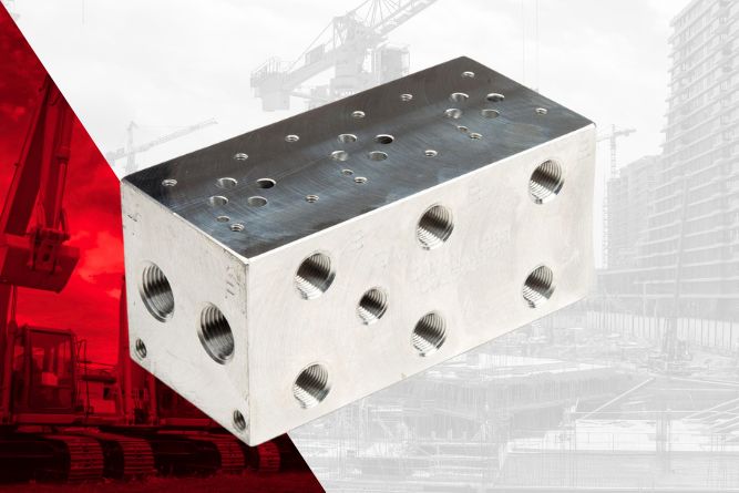
Custom Manifolds
Directional control valves are integral components in hydraulic systems, allowing precise management of fluid flow to perform various tasks. Whether you're designing a hydraulic system or troubleshooting one, understanding directional control valves can significantly improve system efficiency and functionality.
This guide dissects the essentials, applications, and types of directional control valves, providing insights tailored for hydraulic engineers and fluid power professionals.
What Are Directional Control Valves?
Directional control valves regulate the direction of hydraulic fluid in a system. By controlling the fluid’s flow path, these valves determine where energy will be transferred within the system, enabling tasks like lifting, turning, or pushing.
Their operation is based on controlling the spool inside the valve, which can be shifted to open or block specific flow paths.
Key Functions of Directional Control Valves:
- Start or stop fluid flow.
- Change the direction of fluid flow.
- Throttle flow to manage pressure and speed.
Types of Directional Control Valves
Directional control valves vary based on several factors, including the number of flow paths, spools, and their action or center type. Here are the most common classifications:
1. Based on Flow Paths
- 3-Way Valves: Have three ports—one pump line, one return line, and one work port. Commonly used in single-acting cylinders, these valves allow fluid flow in a simple circuit.
- 4-Way Valves: Add an extra work port, consisting of one pump line, one return line, and two work ports. Typically used in double-acting cylinders, these are more versatile and allow greater control over hydraulic flow.
2. Based on Positions
- 3-Position Valves: Feature forward, neutral, and reverse positions to handle dynamic fluid movement.
- 4-Position Valves: Include the same positions as three-position valves but add a flow position, enabling free movement of oil through open work ports.
3. Based on Spool Action
- Spring-Centered Spool Action: Automatically returns the valve to a neutral position when released. Ideal for applications requiring the valve’s default state to be inactive.
- Detent Spool Action: Locks the spool in place once moved, maintaining its set position until manually adjusted.
Special Application – Pressure Release Detent
One unique application is in log splitter control valves, which often include a pressure release detent. This allows the spool to spring back to neutral once a specific hydraulic pressure is reached, ensuring efficiency and safety.
4. Based on Center Type
- Tandem Center: Blocks work ports while allowing oil to flow freely back to the reservoir in neutral. Often used in mobile equipment.
- Open Center: Permits constant flow from the pump to the tank in neutral. Commonly paired with fixed-displacement pumps like gear pumps.
- Closed Center: Blocks all ports in neutral, ensuring no fluid flow. Typically paired with pressure-compensated pumps for applications requiring higher energy efficiency.
Why Are Directional Control Valves Critical in Hydraulic Systems?
The type of directional control valve you select directly impacts system performance. Faulty or incompatible valves can cause inefficiencies, reduced productivity, or even serious damage to components.
Benefits of Well-Chosen Directional Control Valves:
- Precision Control: Direct fluid flow with accuracy, ensuring tasks are performed seamlessly.
- Improved Efficiency: Leverage the right center type (tandem, open, closed) to minimize energy waste.
- Enhanced Safety: Safeguard systems from overpressure through specialized features like pressure release detents.
- Flexibility: Adapt to diverse equipment needs—whether for mobile construction machinery or industrial presses.
How to Choose the Right Directional Control Valve
Selecting the perfect valve involves evaluating the specific needs of your hydraulic system. Here is a structured approach:
1. Understand Flow Requirements
Determine the maximum flow rate your system demands and ensure compatibility with the valve’s capacity. Undersized valves create bottlenecks, while oversized valves can waste energy.
2. Match with Pump Design
Identify pump type—fixed displacement or variable displacement. Open-center valves are best suited to fixed pumps, while closed-center valves work well with variable pumps.
3. Opt for the Right Spool Action
Consider whether spring-centered (automatic return) or detent (manual locking) action is appropriate for your application.
4. Assess Pressure Ratings
Ensure the valve can handle the system's maximum pressure to sustain performance without risk of failure.
5. Account for System Layout
Examine how many work outputs you need to control. Choose between 3-way or 4-way valves based on single-acting or double-acting applications.
6. Prioritize Durability & Quality
Invest in valves from reliable manufacturers that provide robust warranties and technical support.
Applications for Directional Control Valves
Directional control valves are widely used across industries. Here are some examples:
- Agricultural Equipment: Precise control in plows, harvesters, and tillage machines.
- Construction Machinery: Seamlessly manage hydraulic arms in loaders and excavators.
- Material Handling: Govern fluid flow in forklifts and pallet trucks efficiently.
- Industrial Presses: Regulate hydraulic energy in metal forming processes.
- OEM Custom Designs: Adapt solutions to meet unique machine specifications across any industry.
Ensuring System Longevity with Proper Maintenance
Even the best valves require ongoing maintenance for long-term reliability. Follow these best practices:
- Frequent Inspections: Check for leaks, damaged seals, or debris in ports.
- Regular Cleaning: Ensure clear flow paths by removing any contaminants.
- Lubrication: Maintain smooth operation by keeping internal components adequately lubricated.
- Monitor Spool Action: Verify spools return to the appropriate positions during operation.
Build Better Systems with Reliable Directional Control Valves
Choosing the right directional control valve can streamline your operations, reduce downtime, and improve overall system performance. Whether you're tackling a single-acting task or managing complex double-acting machinery, understanding these components ensures you get the most out of your hydraulic system.
Are you ready to take performance to the next level? Explore Bailey International’s diverse range of hydraulic solutions, including premium directional control valves designed to keep you moving forward seamlessly. With expert support and custom engineering options, Bailey International is your trusted partner in hydraulic innovation.
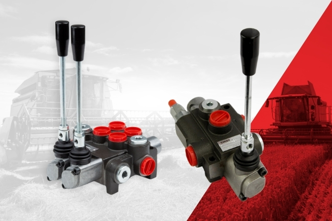
Everything You Need to Know About Directional Control Valves
Hydraulic cylinders are the backbone of heavy equipment operations, found everywhere from construction machinery to agricultural tools. While they may seem like simple components, their production process combines precision, engineering excellence, and stringent quality standards.
Step 1: Receiving and Inspecting Raw Materials
The process begins with raw materials, primarily steel, which arrive in bulk at the manufacturing facility. At Bailey’s Knoxville facility, for instance, over 40,000 lbs of raw steel are received weekly. However, not all that glitters is gold, and not all steel is fit for use.
Quality Assurance
Every incoming batch undergoes rigorous inspection in the Quality Assurance (QA) Lab. This involves verifying material certifications and running tests to ensure the steel meets required specifications. Advanced tools like Faro Arm and 3D scanners create ultra-precise digital blueprints, ensuring every material aligns with optimal tolerances.
Why it matters: Even a small defect in raw material could weaken a cylinder’s performance under high-pressure environments, possibly leading to catastrophic failure.
Step 2: Machining – Precision Above All Else
After the QA checks, the raw material moves to the CNC machining stations. Here, the material undergoes lathing, milling, and drilling to transform it into finely tuned components like tubes, rods, and end caps.
What happens during machining?
- Boring and Threading: CNC lathes create internal bores and threads with pinpoint accuracy. This ensures cylinders achieve perfect seals when assembled.
- Drilling: Holes are drilled into the rods and cylinder tubes at specific angles to integrate ports and attachments.
- Deburring: Edges are smoothed, ensuring no sharp fragments remain, which could damage seals later.
At Bailey, advanced CNC machines can produce up to 120 smaller tubes per day or run larger 8-inch tubes within approximately 8 minutes per piece, drastically cutting production time.
Step 3: Welding – Fusing Strength
Following machining, individual components move to the welding stations, where they are expertly assembled into a cylinder body. MIG and TIG welding, along with robotic welders, ensure strong, durable joints that can withstand extreme pressures.
The accompanying QA process involves verifying that each weld adheres to precise dimensions and structural integrity standards. During inspections, unacceptable seams are flagged immediately and rectified.
Why it matters: Flawless welding is critical for maintaining structural integrity, especially in applications that routinely involve forces of several thousand PSI.
Step 4: Assembly – Bringing it All Together
Once the individual components are complete, the hydraulic cylinder is ready for assembly. Skilled technicians fit seals, rods, and other elements into the cylinder body while ensuring all parts remain contamination-free.
Assembly Highlights
- Seal Installation: High-quality rubber seals are placed with precision to prevent leaks.
- Lubrication: Components are lubricated as required, ensuring smooth operation over extended durations.
- Torque Testing: Bolts, threads, and ports are tightened to exact specifications, ensuring every element fits perfectly.
Assembly teams often work hand-in-hand with QA staff for real-time inspections and corrections at every station.
Step 5: Rigorous Testing – One Cylinder Fit for All
One of the most critical stages in the production process is testing. At Bailey, every cylinder undergoes pressure testing at 1.5 times operating capacity—up to 7500 PSI—to ensure durability and reliability under extreme conditions.
Types of Tests
- Pressure Testing simulates real-world conditions.
- Leak Testing ensures seals maintain integrity under stress.
- Performance Checks verify smooth motion across the cylinder's operational range.
Only after passing these rigorous tests can a cylinder move on to coating and finishing.
Step 6: Coating and Customization
Now that the manufactured cylinder has been tested, it’s prepared for environmental longevity and visual appeal through the painting process. At Bailey, customers can even request custom colors.
Why Paint Matters
The paint layer protects the cylinder against rust, corrosion, and environmental wear, extending its lifespan significantly.
Step 7: Packaging and Shipping
Finally, the finished hydraulic cylinders are meticulously packaged and prepared for shipment. Whether destined for an OEM, distributor, or field mechanic, each cylinder includes clear labeling and accompanying documents like specs and test reports. With Bailey’s strategic warehouse locations and streamlined logistics, components reach most customers within just two days.
Why Precision Matters in Hydraulic Cylinder Manufacturing
The process of creating a hydraulic cylinder is more than just an assembly line; it’s a calculated, carefully monitored sequence of operations. Every step, from selecting raw materials to delivering the finished product, determines the hydraulic cylinder’s overall lifespan, efficiency, and reliability in real-world applications.
Whether you're sourcing cylinders for manufacturing, agriculture, or heavy equipment, choose trusted providers like Bailey International, who prioritize precision, quality, and durability.
Discover Excellence with Bailey International
Want premium hydraulic cylinders that guarantee peak performance? Bailey International delivers unmatched reliability backed by over 40 years of expertise. Explore their extensive range of hydraulic solutions today.

From Raw Materials to High Performance: How a Hydraulic Cylinder is Made
For engineers and technicians working with hydraulic systems, precise measurements are crucial to ensure optimal performance. Measuring a hydraulic cylinder correctly is an essential skill that helps you choose the right component for the job, guaranteeing safety, efficiency, and reliability. This guide outlines the key steps to measure a cylinder effectively, with insights from Bailey International, a trusted name in hydraulic solutions for over 40 years.
Why Accurate Measurement Matters
Hydraulic cylinders are used across industries like agriculture, construction, manufacturing, and transportation. An inaccurately measured cylinder can lead to inefficiencies, decreased performance, or even mechanical failures. Taking precise measurements ensures that the cylinder you choose will meet the demands of your specific application.
Key Measurements for Hydraulic Cylinders
1. Retracted Dimension
The retracted dimension is one of the most important metrics for selecting a hydraulic cylinder. This measurement determines the cylinder's length when fully closed.
How to Measure:
- Start by identifying the center of the pin at one end of the cylinder.
- Measure to the center of the pin at the other end, ensuring the cylinder is fully retracted.
Why It Matters:
The retracted dimension ensures that the cylinder fits within the designated space when not in use. This is particularly critical for applications with limited installation space, such as compact agricultural equipment or industrial machinery.
2. Stroke Length
The stroke is the distance the piston rod travels out of the cylinder. Think of the stroke as the functional movement of the cylinder.
How to Measure:
- Measure from the center of one work port to the center of the other work port.
- Deduct approximately two inches from your measurement to account for the piston inside the cylinder.
Why It Matters:
The stroke length determines how much linear motion the cylinder can deliver. Accurate stroke measurements are essential for applications where precision and range of motion are critical, such as material handling or ground support equipment.
3. Bore Dimension
The bore dimension refers to the inside diameter of the cylinder tube. This measurement is directly related to the push force the cylinder can generate.
How to Measure:
- Determine the inside diameter of the tube that encases the body of the cylinder.
Why It Matters:
The bore dimension defines the hydraulic cylinder's capacity to generate force. Larger bore sizes result in greater push forces, making this measurement vital for high-load applications like mining or construction industries.
Additional Considerations for Cylinder Selection
While retracted dimensions, stroke lengths, and bore dimensions are the primary measurements, here are a few additional factors to keep in mind:
1. Operating Pressure
Hydraulic systems operate under various pressure levels. Always ensure the cylinder you select can handle the operating pressure specified for your application. Bailey International offers detailed specifications for all of its products to help you make an informed choice.
2. Mounting Options
The type of mounting (e.g., clevis, flange, trunnion) affects how the cylinder interacts with the surrounding components. Make sure the mounting style aligns with your machinery's design.
3. Rod Material and Finish
The material and surface finish of the piston rod determine its resistance to wear and corrosion. Applications exposed to harsh environments, like marine or mining operations, may require specialized coatings or treatments.
Common Applications of Hydraulic Cylinders
Accurate measurements ensure that your cylinder performs reliably across a wide range of industries:
- Agriculture: Soil preparation, plowing, or hitch systems
- Construction: Heavy machinery like excavators and cranes
- Material Handling: Forklifts or conveyor systems
- Industrial Operations: Press machines and automated systems
- Transportation: Brake and suspension systems for railroads
Hydraulic systems can vary significantly depending on their applications. If you're unsure about measuring a hydraulic cylinder or selecting the right one, Bailey International's team of experts is here to help. With over four decades of experience and a vast catalog of hydraulic components, Bailey provides solutions you can trust.
Why Choose Bailey International?
Bailey isn't just a supplier—it's a partner for success. Here’s how Bailey stands out:
- Unmatched Expertise: Over 40 years of experience in hydraulic and electronic solutions.
- Custom Solutions: If standard components don’t match your needs, Bailey's MVP Program offers fully customized options.
- Reliable Support: From design to delivery, Bailey provides comprehensive assistance to ensure optimal performance.
- Fast Shipping: Strategically located warehouses allow Bailey to deliver components quickly, minimizing downtime.
Browse Bailey's hydraulic cylinders and more at www.baileyintl.com.
Proper measurement of hydraulic cylinders is the foundation of any efficient and functional hydraulic system. By following the steps outlined in this guide, you can ensure that every measurement is precise and your cylinder selection is ideal for the task at hand.
When precision matters most, partner with a name you can rely on. Contact Bailey International for expert guidance or browse their extensive collection of hydraulic components to find the perfect fit for your needs.
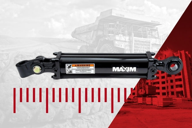
How to Measure a Hydraulic Cylinder
Understanding the precise specifications of a gear pump is critical for hydraulic engineers, technicians, and mechanics. Whether you need to replace an existing component, verify capacity, or plan for optimal system performance, knowing how to accurately measure your gear pump is an essential skill.
This guide provides step-by-step instructions on how to measure the cubic-inch displacement of a gear pump, using clear and accurate techniques that will save you time and ensure precision. Follow along for professional advice grounded in expertise and reliability.
What You'll Need
Before starting, ensure you have the following tools on hand:
- A caliper (digital or vernier for precise measurements)
- A clean work surface for disassembling the pump
- The gear pump in question
It’s also ideal to have a pen and paper or a device for recording your measurements and calculations.
Step 1: Disassemble the Gear Pump
To measure the cubic-inch displacement of a gear pump, you first need to access internal components. Follow these steps to carefully disassemble the pump:
- Remove the four bolts holding the pump together. Be sure to place the bolts in a secure location to avoid losing hardware during reassembly.
- Take off the end plate. This will expose the gear chamber.
- Proceed to remove the gear chamber, followed by the bearing carrier.
- Extract the gear itself carefully to avoid any potential damage. Handle these components with precision to maintain the structural integrity of each part.
- Finally, detach the front plate, allowing full access to the internal structure.
Properly disassembling the pump is critical to gaining accurate measurements. Ensure all components are clean and free of debris before proceeding to the measurement process.
Step 2: Take Precise Measurements
Now that the pump is disassembled, it’s time to collect the necessary dimensions to calculate the cubic-inch displacement. Use your caliper for maximum accuracy and measure the following:
1. Length Across the Gear Chamber
With the caliper, measure the length of the gear chamber from top to bottom. Ensure the caliper is correctly aligned for a precise reading.
2. Diameter Across One Gear Chamber
Next, measure the diameter across one gear chamber. This dimension is crucial for calculating the circular cross-section, so accuracy is paramount.
3. Width of the Gear Teeth
Finally, measure the width of one gear itself. This measurement will factor into determining the overall volume the gear displaces as it rotates.
Keep your measurements recorded in consistent units—typically in inches for hydraulic applications in the U.S.—to ensure uniformity during the calculation process.
Step 3: Calculate the Cubic-Inch Displacement
Once you have each of these measurements recorded, you can determine the cubic-inch displacement using a simple formula. For a gear pump, the displacement generally follows this calculation:
Cubic Inch Displacement = π × (Chamber Diameter ÷ 2)² × Chamber Length × Gear Width
Here’s a breakdown of the formula:
- π (Pi): Constant (3.14159)
- Chamber Diameter ÷ 2: Determines the radius
- Chamber Length: The length of the gear chamber
- Gear Width: Thickness of the gear which defines the displacement during rotations
Calculate the result to determine the exact cubic-inch displacement of your gear pump. This number provides crucial insight into the pump’s capacity and helps match it to the right hydraulic system requirements.
Why Accurate Measurements Matter
Correct measurements of a gear pump are key to achieving optimized hydraulic system performance. Here’s why it’s important:
- System Efficiency: Understanding displacement ensures your pump meets the flow rate requirements of your system.
- Preventing Overloading: A mismatch in capacity could lead to pressure imbalances, causing undue stress on other components.
- Improved Component Longevity: Proper sizing and matching minimize wear and tear, extending system uptime and reducing costs.
By following these steps, you'll have the accurate data needed to maintain or enhance the efficiency of your hydraulic system.
Expert Support and Custom Solutions from Bailey
If you still have questions or require specialized assistance, Bailey International provides expert support backed by over 40 years of leadership in hydraulics. Our seasoned team is dedicated to helping you make informed decisions with tailored solutions for your unique needs.
Looking for a new gear pump to meet precise specifications? Browse Bailey’s extensive catalog of high-quality gear pumps, hydraulic valves, and other components designed to optimize your operations.
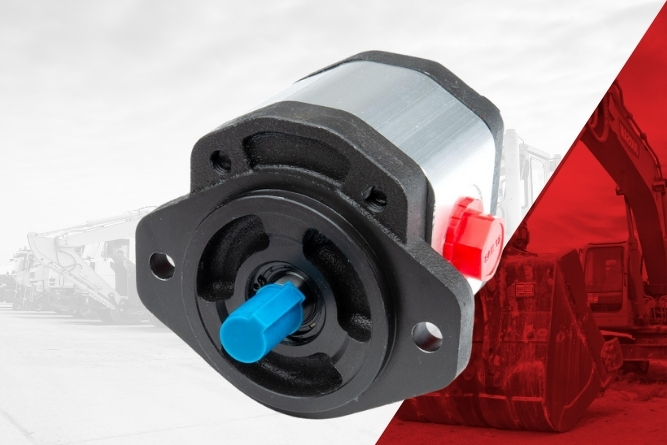
How to Measure a Gear Pump
Directional control valves are essential components in hydraulic systems, and understanding how to install one can streamline operations across various applications. Whether you're an experienced hydraulic engineer or a professional working in construction, ensuring the proper installation of a control valve is a fundamental skill. This guide will break down the process, highlight key considerations, and provide insights into efficient hydraulic valve installation.
Why Directional Control Valves Matter
Directional control valves manage hydraulic fluid flow, allowing operators to control the direction and pressure within hydraulic systems. These are integral for applications like controlling actuators, motors, or cylinders in machinery. Proper installation ensures equipment reliability, system efficiency, and long-term performance.
Step-by-Step Guide to Plumbing a Directional Control Valve
Follow these steps to ensure the correct installation of your directional control valve.
Step 1. Identify Valve Components
Start by inspecting your valve. Look for clear labels for the pump line (P), tank line (T), and work ports. These designations guide the direction of hydraulic fluid flow and are crucial for effective setup.
- The pump line (P) connects to your hydraulic pump.
- The tank line (T) directs fluid back to the reservoir or tank.
- Work ports control the associated actuators or machinery.
Additionally, some valves include arrows indicating flow direction. Use these markings to double-check each connection point.
Step 2. Gather the Proper Tools and Materials
To streamline the installation, ensure you have the following tools and materials ready:
- Hydraulic hoses and fittings.
- Wrenches suitable for your valve's connections.
- Thread sealant or PTFE tape to prevent leaks.
- A clean workspace to avoid dirt or contaminants entering the system.
Step 3. Connect the Pump Line to the Valve
Locate the P (pump line) port on the valve and securely attach the hydraulic line connected to the pump. This line supplies pressurized fluid to the system, so double-check that the fittings are tight and free from leaks to avoid pressure loss.
Step 4. Attach the Tank Line
Next, connect the T (tank line) port on the valve to the hydraulic tank or reservoir. This line provides a return path for the fluid after completing each cycle. Proper connection avoids fluid buildup and ensures system efficiency.
Step 5. Connect Work Ports to Machinery
On top of the valve, you’ll find the work ports, which control actuators, such as a hydraulic cylinder, motor, or other components. Each work port directs hydraulic fluid to corresponding equipment. Double-check the connections to match your system's specifications and verify that the direction of flow aligns correctly for desired operations.
Step 6. Secure and Test the System
Once all connections are complete, secure the valve in place, ensuring it is firmly mounted to prevent movement. Turn on the hydraulic system and perform a preliminary test:
- Check for leaks around the connections.
- Verify that fluid flows in the correct direction.
- Operate actuators to ensure proper control and functionality.
Testing ensures that your setup is accurate and prevents future operational issues.
Common Mistakes to Avoid
When plumbing a directional control valve, there are a few common pitfalls to watch out for:
- Reversed Connections – Attaching the pump line to the tank port or vice versa will result in system failure. Always double-check labels and flow directions before proceeding.
- Loose Fittings – Improperly tightened connections can cause leaks, inefficiency, or even complete system shutdown.
- Neglecting System Pressure Ratings – Ensure the valve you’re using matches the pressure and flow requirements of your hydraulic components.
Optimizing Valve Installation with Expert Support
If you’re a professional looking to simplify hydraulic installations or require tailored solutions, consider working with industry experts like Bailey International. With over 40 years of experience, Bailey provides high-quality hydraulic components, reliable technical support, and custom solutions for diverse industries, including construction, agriculture, and transportation.
Visit Bailey International to explore their product catalog and elevate your hydraulic systems today.
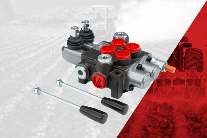
How to Plumb a Directional Control Valve
Properly calibrating your hydraulic system is essential for maintaining efficiency, safety, and performance. One critical aspect is setting your relief pressure. This process ensures your system is working correctly and prevents damage caused by over-pressurization.
If you’re new to hydraulic system maintenance or just need a refresher, this guide will walk you through how to set your hydraulic system's relief pressure step-by-step. We’ll make sure you understand what’s required and empower you to get it right every time.
Why It’s Important to Set the Relief Pressure Properly
Relief pressure acts as your system’s safety net. When hydraulic fluid pressure rises too high, it can damage hoses, pumps, cylinders, and other components. High pressure may also increase wear and tear, reduce the lifespan of your hydraulic system, and compromise safety.
By setting your relief pressure correctly, you ensure that your equipment runs efficiently without unnecessary strain on its components. Additionally, having the right pressure protects operators and the surrounding environment from the risks of a pressure-related failure.
Follow these carefully outlined steps, and you’ll have your system calibrated safely and effectively.
Step 1: Determine Your System’s Current Pressure
Start by finding out your hydraulic system’s existing pressure level. To do this, you’ll need to operate the system and use a pressure gauge to monitor the pressure. Create pressure in the system by activating it as you would during normal operations, watching the pressure gauge for measurements.
Important Tips:
- Always use a high-quality and calibrated pressure gauge for accurate readings.
- Ensure the gauge is compatible with your specific hydraulic system to avoid errors.
Knowing your current pressure is vital for adjusting the relief pressure to meet your specific equipment's requirements.
Step 2: Consult Your Equipment Manual for Pressure Requirements
Not all systems operate at the same pressure. The correct relief pressure will depend on the type of equipment you’re working with and its specific application. Check your equipment’s product manual or contact the manufacturer for guidance on recommended pressure levels.
Pro Tip: When in doubt, don’t guess. Start low and gradually increase pressure if you lack clarity on the requirements, as over-pressurization could damage your system.
Step 3: Relieve Pressure and Loosen the Jam Nut
Before making any adjustments, power down the system or ensure that it is not under any pressure. Once the system is off, locate the directional control valve, specifically the relief valve assembly, within the hydraulics mechanism.
Now, loosen the jam nut (sometimes called a locknut) by turning it counterclockwise. This allows you to adjust the relief valve safely and effectively.
Safety Reminder:
- Wear PPE (Personal Protective Equipment) while working on hydraulic systems.
- Confirm that all moving components have stopped before loosening any parts.
Step 4: Adjust the Relief Valve Screw
Using a screwdriver or the appropriate tool for your valve, adjust the relief valve screw to increase or decrease the pressure. Here’s how it works:
- Turning clockwise increases relief pressure.
- Turning counterclockwise decreases relief pressure.
Tip: Small changes can have a dramatic effect on your system. Begin with slight turns to see how the pressure changes. For most valves, a quarter turn is sufficient to make significant adjustments.
Step 5: Tighten the Jam Nut and Test the System
Once the adjustment screw is in the correct position, tighten the jam nut to secure it. Without turning the screw further, carefully start your system back up. Gradually apply pressure while monitoring the system’s pressure gauge closely.
- If the system pressure meets your requirements, you’re done!
- If it’s too high or low, don’t worry. Repeat the adjustment process by loosening the jam nut and fine-tuning the screw until the desired relief pressure is achieved.
Step 6: Test and Verify
It’s essential to double-check your work for accuracy and safety. Operate your hydraulic system under normal working conditions and keep an eye on the pressure gauge for any unexpected fluctuations. Once everything is stable and functioning within your equipment’s recommended pressure range, the setup is complete.
Troubleshooting:
- Does the pressure still exceed the target range? Reinspect the relief valve to ensure everything is properly secured and adjusted.
- Is the gauge reading staying too low? There may be other components contributing to insufficient pressure, such as blockages or a malfunctioning pump.
Tips for Success
- Document your changes. Keep a record of the final relief pressure you set. This will make future calibrations easier to perform.
- Schedule regular checks. Relief valves can wear out over time if your system is exposed to demanding operations. Routine checkups ensure they remain effective.
- When in doubt, call the experts. The hydraulic specialists at Bailey International are ready to guide you through troubleshooting and provide tailored recommendations for your system.
Achieving Precision with Bailey International
Setting your hydraulic system relief pressure is a fundamental step in maintaining safety, efficiency, and longevity. But it doesn’t end there. At Bailey International, we deliver solutions tailored to your specific needs—whether it’s sourcing top-tier components or providing expert advice.
From directional control valves to pressure gauges, our extensive product range has the tools and resources you need to ensure smooth operations.
Looking for more guidance? Explore our educational resources or talk to one of our technicians today to ensure your systems operate at peak performance.
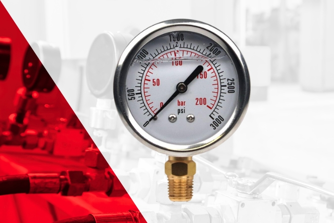
How to Set Your Hydraulic System Relief Pressure
When it comes to hydraulic systems, gear pumps are the heart of countless applications across industries, like construction, oil & gas, and manufacturing. With their durability, efficiency, and reliability, gear pumps are among the most widely used pumps in the world today. This guide explains what sets gear pumps apart, how they work, and how to get the best performance from them in your hydraulic systems.
What Are Gear Pumps?
A gear pump is a type of positive displacement pump that uses the meshing of gears to pump oil or other fluids. Their primary function is to generate flow, while the resistance—caused by valves, motors, or cylinders in the system—creates the necessary pressure to drive the operation.
Key characteristics of gear pumps:
- Durability: Gear pumps can handle contaminated fluids better than many other pump types, making them ideal for demanding environments.
- Affordability: They are generally more cost-effective than vane or piston pumps, making them a popular choice for many applications.
- Simplicity and Reliability: With fewer complex components, gear pumps are easier to maintain and highly reliable under continuous use.
How Do Gear Pumps Work?
The operation of gear pumps follows a straightforward and highly efficient process:
- Intake of Fluid: The gears rotate, creating a vacuum that draws oil into the pump.
- Movement of Fluid: The fluid is carried around the outer chamber of the pump, trapped between the gear teeth and housing.
- Pressurization and Output: The gears' rotation pushes the fluid out through the outlet port, creating flow within the hydraulic system.
Gear pumps have a fixed displacement, which means the same amount of fluid is moved per rotation of the gears. This displacement is measured in cubic inches or cubic centimeters, depending on the application.
Watch a gear pump in action by checking out our demo video on one of our gear pump solutions.
Types of Gear Pumps
Gear pumps come in a variety of shaft designs to meet the needs of specific applications. Common types include:
- Spline Shaft Pumps: Features multiple teeth for efficient torque transfer.
- Keyed Shaft (KY) Pumps: Uses a key to lock the shaft and gear together for secure operation.
- Tang Shaft Pumps: Ideal for specific, precise applications requiring unique shaft configurations.
Regardless of the shaft type, the functional principles of gear pumps remain the same.
Applications of Gear Pumps Across Industries
1. Construction
From excavators to bulldozers, gear pumps are the driving force behind the hydraulic systems that power heavy construction equipment. Their durability and ability to handle contamination make them ideal for rugged construction environments.
2. Oil & Gas
Gear pumps play a crucial role in upstream and midstream oil and gas operations, handling tasks such as fluid transfer and pressure boosting. Their reliability ensures uninterrupted operations in mission-critical environments.
3. Hydraulic Engineering
For hydraulic engineers designing cutting-edge systems, gear pumps offer a balance of simplicity and performance. They provide reliable flow generation, forming the foundation of any efficient hydraulic setup.
Installation Tips for Gear Pumps
Proper installation is critical to ensure long-term performance and reliability. Follow these steps for optimal setup:
- Align the Shaft: The pump shaft must be concentric with the driving motor or engine to avoid misalignment and wear.
- Select the Right Coupler: Use an appropriate coupler to securely connect the pump to the motor. Bailey offers a range of foot mounts, brackets, and couplers tailored to your needs.
- Use Clean Oil: Contaminants can wear down the gears over time. Employ a suction strainer and a filter to keep the hydraulic fluid clean.
- Secure Mounting: Proper mounting ensures stability and prevents unnecessary vibrations or stress on the pump.
Need assistance choosing the right components? Contact Bailey’s technical team for free expert guidance.
Maintenance Best Practices for Gear Pumps
Even the most durable pumps require regular maintenance to maximize their lifespan and efficiency. Here are a few best practices:
- Keep the Fluid Clean: Regularly replace or clean filters and strainers to prevent contamination.
- Inspect Seals: Leaky seals around the shaft or housing can lead to inefficiency. Replace worn-out seals promptly.
- Monitor for Wear: Check gears and other internal components for signs of wear and replace them as needed to avoid a complete pump failure.
- Service Schedule: Establish a routine maintenance schedule to proactively address issues before they become critical.
Gear pumps from Bailey are designed to last for years with proper care. Our experts can help extend your pump’s life by providing replacement parts, such as seals and couplers.
Bailey’s Gear Pump Solutions at a Glance:
- Premium Quality: High-performance materials and precise engineering.
- Custom Solutions: Tailored components to meet your unique requirements.
- Expert Support: Dedicated technical assistance for seamless installation and maintenance.
Boost efficiency and reliability in your hydraulic systems by choosing gear pumps from Bailey. Contact us or explore our online catalog to find the perfect solution for your application.
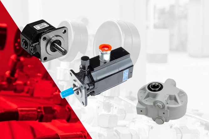
The Essential Guide to Gear Pumps for Hydraulic Industry Professionals
Hydraulic applications are integral to industries such as construction, agriculture, mining, and manufacturing. The systems powering these machines rely on precise controls to perform efficiently and reliably. Yet, as these industries evolve, off-the-shelf hydraulic controls often fall short of meeting the unique challenges and demands of specialized machinery. That’s where custom hydraulic controls step in, offering tailored solutions to enhance performance, safety, and efficiency.
Here, we’ll explore the importance of customized hydraulic controls, highlight their key benefits, and introduce you to Bailey Electronics, a leader in tailored solutions for electronic hydraulic applications.
Why Customization Matters
Off-the-shelf hydraulic controls might seem like a convenient choice. However, most standard options are designed with broad applications in mind, leaving gaps in performance for specialized needs. Here’s why customization is essential for hydraulic applications:
- Unique Machine Requirements
Every hydraulic machine has specific performance requirements. Off-the-shelf controls may not provide the precision and responsiveness needed to meet those demands.
- Operational Efficiency
Standard controls can lead to inefficiencies as they lack the adaptability to meet real-world operating conditions.
- Industry-Specific Demands
Equipment used in construction, mining, and agriculture faces unique challenges such as harsh environments and high operating pressures. Custom controls are built to withstand these conditions, ensuring durability.
Custom hydraulic controls address these gaps, providing a tailored fit for the operational needs of complex machinery.
Benefits of Custom Hydraulic Controls
Tailored hydraulic controls deliver several advantages over generic alternatives, boosting overall machine performance:
1. Enhanced Performance
Custom controls are designed for precision, delivering smoother motion, quicker response times, and greater overall system accuracy. This is critical for applications like material handling, where small errors can disrupt workflows.
2. Improved Safety
With custom designs, safety features can be integrated to match specific operational risks. For example, emergency stop systems or controls with better ergonomics reduce the likelihood of accidents, keeping operators safe.
3. Maximum Efficiency
Tailored solutions reduce energy consumption by ensuring that hydraulic systems only operate within their optimal parameters. This lowers costs while extending equipment lifespan.
4. Operator Comfort
Human-centric designs, such as ergonomic joysticks and armrests, prioritize operator comfort and reduce fatigue, enabling longer and more productive working hours.
5. Scalability and Adaptability
Custom controls allow for integration with modern technologies, such as IoT (Internet of Things) sensors, to offer real-time data tracking, enabling proactive maintenance and flexible system upgrades.
These advantages aren’t just desirable—they’ve become necessary for businesses looking to stay competitive in demanding markets.
Meet Bailey Electronics
When it comes to custom solutions, Bailey Electronics sets the gold standard. With decades of experience and a global reach, Bailey works closely with machinery manufacturers, industrial designers, and engineers to deliver tailor-made hydraulic controls that exceed expectations.
Expert Engineering
Bailey Electronics boasts a team of highly skilled engineers who specialize in creating innovative solutions for diverse hydraulic applications. Their deep industry knowledge allows for precise customization based on each client’s specifications.
Global Reach, Local Expertise
Serving industries worldwide, Bailey Electronics combines its global expertise with a commitment to local customer needs. Whether you’re designing agricultural machinery or manufacturing equipment for mining operations, Bailey supports you with tailored solutions and unmatched reliability.
Quality and Rigorous Testing
Bailey Electronics places an unwavering emphasis on quality. Every product is built with premium materials, including high-grade metals, plastics, and electronic components, designed for unmatched resilience in their field.
Stringent Quality Standards
Bailey Electronics subjects all products to rigorous testing protocols to ensure compliance with the highest industry standards. These tests cover durability, performance, and safety, so customers can trust their products in even the most challenging conditions.
Certified Excellence
Bailey Electronics is proud to hold ISO certifications, including ISO 9001 for quality management, ISO 14001 for environmental management, and ISO 45001 for occupational health and safety. These certifications reflect the company’s steadfast dedication to delivering superior, reliable solutions.
When you choose Bailey Electronics, you’re not just investing in a product—you’re investing in peace of mind.
Customization That Meets Your Needs
At Bailey Electronics, customization is not an afterthought—it’s their core strength. Their client-centric approach ensures that every solution is tailored precisely to meet specific challenges.
- End-to-End Collaboration
Bailey Electronics works closely with clients every step of the way, from ideation to delivery. Their engineers ensure the final product aligns perfectly with your operational goals.
- Wide Range of Customizable Products
Whether you need joystick controls, throttle systems, or hydraulic sensors, Bailey Electronics offers a diverse range of customizable components to fit seamlessly into your machinery.
- Future-Forward Solutions
Bailey’s custom controls are designed to integrate with advanced technologies, ensuring compatibility with IoT systems, automation, and other modern engineering advancements.
Your needs are never generic—why should your hydraulic controls be?
Make the Switch to Custom Hydraulic Controls
Hydraulic systems drive productivity, safety, and efficiency across industries. Custom controls take this a step further, allowing businesses to optimize performance, meet specific operational challenges, and ensure long-term reliability.
Bailey is your trusted partner in creating custom hydraulic controls tailored to your unique requirements. With their dedication to engineering excellence, quality standards, and client collaboration, they’ve earned their place as a leader in the industry.
Don’t settle for less. Experience the difference custom controls can make for your hydraulic applications. Contact Bailey Electronics today to explore tailored solutions designed to power your success.
[Call to Action Button] Learn More About Custom Controls
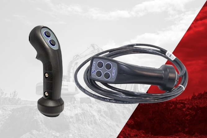
The Importance of Custom Controls for Your Hydraulic Applications
Hydraulic motors play a pivotal role in modern hydraulic systems, delivering the rotary force required to power machinery across industries. Whether you're an engineer designing industrial equipment, a hydraulic technician troubleshooting systems, or a construction professional seeking reliable components, understanding how hydraulic motors work and their applications is essential. This guide offers an in-depth look at hydraulic motors, from their mechanics to their practical uses, and tips for ensuring you're using the right motor for the job.
What Are Hydraulic Motors?
Hydraulic motors are key components in hydraulic systems, transforming fluid energy into mechanical energy. Essentially, they take pressurized fluid, often oil, and generate torque and rotational force to drive machinery. These motors are classified as actuators, meaning they operate at the end of the hydraulic line to perform a specific task—in this case, producing rotary motion.
For example:
- A hydraulic cylinder converts fluid power into linear motion, ideal for tasks like lifting or pressing.
- A hydraulic motor, meanwhile, manipulates fluid energy for rotary motion, offering torque to spin wheels, conveyor belts, or other components.
Types of Hydraulic Motors
The BM series motors, like those at Bailey International, exemplify versatility and strength in hydraulic motor design. Specific motor variations include:
- G-Rotor Motors: Named for the internal rotor component, these offer effective torque through their innovative design.
- G-Roller Motors (with roller bearings): These enhance operational efficiency by offering smoother rotation and reducing internal friction.
Why Not Simply Use a Hydraulic Pump as a Motor?
While gear pumps can technically be used as motors, they are not designed to handle the stress and directional flexibility required of motors. Hydraulic motors are specifically built for tasks like running in series (e.g., multiple motors powering a conveyor belt) or operating under bi-directional conditions. Using a pump as a motor may create inefficiencies and increase wear over time, making it an unsuitable choice for complex tasks.
Key Applications of Hydraulic Motors
Hydraulic motors excel in various fields, providing essential power to drive systems in demanding situations. Here are some common applications across industries:
1. Construction Equipment
Hydraulic motors power heavy machinery such as excavators, cranes, bulldozers, and drills. Their ability to withstand high pressures and deliver consistent torque makes them ideal for operating under rugged conditions.
2. Conveyor Systems
Motors in the BM series, like those featured by Bailey, are perfect for conveyor applications. Picture a wood processing plant where multiple motors are placed in series to drive conveyor belts continuously, ensuring the smooth flow of materials.
3. Agriculture
Think of tractors or harvesters where hydraulic motors power rotating components like mowers or seed-drilling systems. These high-torque motors ensure reliable performance that's critical for large-scale farming operations.
4. Industrial Machines
From injection molding machines to presses, hydraulic motors are indispensable in ensuring industrial equipment operates with precision and efficiency.
5. Marine and Transportation
Hydraulic motors also play a significant role in ship steering mechanisms, winches, and vehicle applications where controlled rotary motion is essential.
Advantages of Using Hydraulic Motors
Why choose hydraulic motors for your applications? Here are some clear benefits:
- High Torque at Low Speed: Hydraulic motors can provide substantial force even at relatively low operational speeds.
- Durability: Designed to handle high pressures, these motors are built to last, even in challenging environments.
- Compact and Efficient Design: Hydraulic motors offer a high power-to-weight ratio, making them suitable for space-constrained setups.
- Bi-Directional Operation: Many motors, including Bailey’s BM series, can spin both clockwise and counterclockwise, offering versatility for different systems.
- Scalability: Motors come in various displacements and sizes, allowing engineers and technicians to find the perfect match for their specific needs.
Choosing the Right Hydraulic Motor
Selecting the right hydraulic motor for your application is crucial for ensuring operational efficiency and longevity. Here’s how you can make sure you’re getting the right fit:
1. Determine Your Performance Requirements
Understand your torque, speed, and pressure needs. This will help narrow down your motor choices by size and performance capacity.
2. Evaluate the Application
For example, if you need a motor for conveyor systems, consider whether the motor can be run in series and if it’s designed to handle pressure on both sides.
3. Account for Directionality
Choose motors that are bi-rotational if your system demands movement in both clockwise and counterclockwise directions.
4. Consider Motor Type
Decide between basic motors like G-Rotor and more advanced G-Roller motors, which offer greater efficiency and support for high-load applications.
5. Consult Experts
Reputable providers like Bailey International offer engineering support to help you determine the best fit. Their MVP (Motors, Valves, and Pumps) program simplifies the process for tailored hydraulic solutions.
Maintaining Hydraulic Motors for Longevity
Once you’ve selected the right motor, proper maintenance is vital to its performance. Here are a few tips:
- Regular Inspection: Check for leaks, worn components, or unusual noises during motor operation.
- Use Clean Hydraulic Fluid: Contaminated fluid can damage motor components over time.
- Follow the Manufacturer’s Guidelines: Adhering to prescribed operating conditions ensures optimal performance and prevents unnecessary wear.
Why Choose Bailey International for Hydraulic Motors?
Bailey International is a trusted leader in hydraulic solutions, with over 40 years of experience. Here’s why professionals turn to them for motors:
- Comprehensive Range: Bailey offers the BM series with various displacements and configurations to fit different needs.
- Expert Support: Their technical and engineering teams provide guidance on motor selection and troubleshooting.
- Reliable Warranty: All motors come with robust warranties, reflecting Bailey’s commitment to quality and performance.
- Quick Delivery: Strategically located warehouses ensure fast shipment, minimizing downtime.
If you’re unsure about which hydraulic motor is right for you, Bailey’s MVP center is just a call away, ready to assist with your project.
Optimize Your Systems with the Right Hydraulic Motor
Hydraulic motors are the backbone of countless industrial, agricultural, and construction systems. Whether powering conveyor belts or giant excavators, these components translate hydraulic energy into reliable rotary motion, enabling the seamless operation of complex machinery.
To ensure you get the right motor for your needs, focus on understanding your application, performance requirements, and system constraints. And if you need expert advice, Bailey International’s experienced team is here to help.
Find the perfect hydraulic motor for your application today. Contact Bailey or visit our website to explore our wide selection of hydraulic motors, including the BM series, and experience the Bailey advantage.
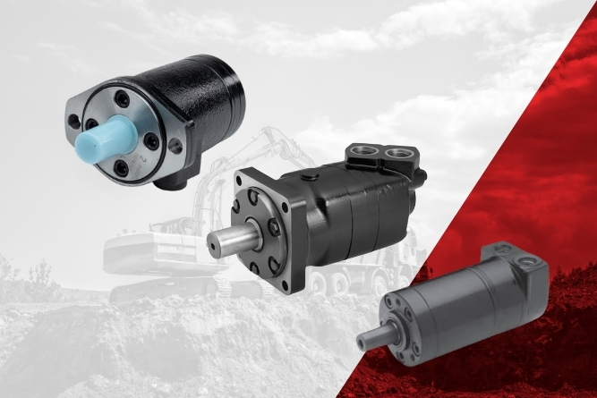
Understanding Hydraulic Motors and Their Applications

Customer Support, Engineer Expertise
Reliable support when you need it. Our team of customer service agents and engineers is dedicated to keeping your operations running smoothly. With expert guidance, technical resources, and Lunchbox training programs, we empower you to get the most out of your hydraulic products.