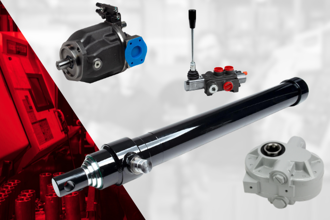
Hydraulics
Knowledge Hub
Hydraulics
Knowledge Hub
We’re more than just a provider—we’re your your trusted resource for all things fluid power. From calculators and tools to expert articles and videos, we provide the knowledge you need to tackle any job with confidence.
We’re more than just a provider—we’re your your trusted resource for all things fluid power. From calculators and tools to expert articles and videos, we provide the knowledge you need to tackle any job with confidence.


Expert Guidance, Dedicated Support
Keeping your operations running at peak performance is our priority. Our expert support team is ready to assist you pre- and post-sale. With Lunchbox training programs and technical guidance, we provide the knowledge and resources you need to make the most of your hydraulic equipment.
Our Latest Educational Articles
For over 40 years, Bailey has been a trusted leader in the manufacturing and distribution of hydraulic and electronic solutions. Dive into our educational content to expand your knowledge and discover how our expertise can support your success.
For OEM manufacturers, hydraulic component selection is an engineering decision, a reliability decision, and ultimately a customer experience decision.
The wrong component can create inefficiencies and damage customer confidence. The right component, however, can improve performance and help OEMs deliver equipment that consistently performs under demanding conditions.
So how do manufacturers make the right choice?
Start With the Application, Not the Component
One of the most common mistakes in hydraulic system design is focusing on individual products before fully understanding the application's requirements.
Before selecting cylinders, pumps, valves, or power units, manufacturers should evaluate:
- Operating pressure requirements
- Flow rate demands
- Load capacities
- Duty cycles
- Environmental conditions
- Available installation space
- Regulatory or safety requirements
A hydraulic system designed for material handling equipment faces very different challenges than one used in construction or industrial manufacturing.
The question should never be, "Which hydraulic component should we buy?"
The better question is, "What does the equipment need to achieve?"
Once that answer is clear, component selection becomes far more strategic.
Understand How Components Work Together
Hydraulic systems are ecosystems. Every component influences the performance of the others.
A high-performance cylinder cannot compensate for an undersized pump. A premium valve cannot overcome contamination caused by poor filtration. Even the most advanced hydraulic system will struggle if flow rates, pressure ratings, and operating conditions are mismatched.
Successful OEMs evaluate hydraulic systems as complete operating environments rather than collections of individual parts.
The goal is not simply selecting quality components. The goal is selecting components that function together efficiently and reliably throughout the equipment's lifecycle.
Focus on Performance Requirements First
Every hydraulic component has operational limits. Exceeding them often leads to premature failure.
When evaluating hydraulic components, OEMs should pay particular attention to:
Pressure Ratings
Components must be capable of handling both normal operating pressures and potential pressure spikes. Industry experts commonly recommend building in an adequate safety margin rather than selecting components that merely meet minimum operating requirements.
Flow Requirements
Flow directly impacts equipment speed and responsiveness. An incorrectly sized pump can create bottlenecks that reduce productivity and increase energy consumption.
Duty Cycle
Will the equipment operate intermittently or continuously? Components that perform well in light-duty applications may not withstand demanding, high-cycle environments.
Environmental Conditions
Extreme temperatures, moisture, dirt, vibration, and chemical exposure all influence component longevity. Components should be selected for the environments where equipment will actually operate.
Reliability Is Often More Valuable Than Maximum Performance
Many OEMs fall into the trap of prioritizing maximum specifications.
Higher pressure ratings. Higher flow capacities. More advanced features.
But customers rarely purchase equipment because a component has the highest specification on paper.
They purchase equipment because it works consistently.
Reliability often creates greater long-term value than peak performance.
A hydraulic system that operates efficiently for years with minimal downtime typically delivers a stronger return on investment than one designed solely to maximize output.
Consider Serviceability and Maintenance Early
The best hydraulic systems are designed with maintenance in mind from the beginning.
OEMs should evaluate questions such as:
- Are replacement components readily available?
- Can technicians easily access service points?
- Are filtration systems easy to inspect and replace?
- Are standard components available across multiple machine models?
Maintenance considerations often receive less attention during design phases, yet they significantly influence equipment ownership costs.
Customers remember how easy equipment is to maintain just as much as they remember how well it performs.
Don't Overlook Supplier Expertise
Hydraulic component selection has become increasingly complex as equipment demands continue to evolve, which is why component suppliers should be viewed as strategic partners rather than transactional vendors.
Experienced hydraulic suppliers can help manufacturers evaluate application requirements and identify compatibility issues.
Every pump, valve, cylinder, hose, and fitting contributes to overall system performance. When those components are selected strategically, OEMs gain a competitive advantage.
The most successful manufacturers understand that hydraulic components are not just parts inside a machine. They are critical building blocks of equipment reliability, customer satisfaction, and long-term business growth.
Choosing the right hydraulic components is about engineering confidence into every machine that leaves the production floor.
Talk with a Bailey equipment specialist today. We'll help you identify the right hydraulic and/ or electronic components, optimize system performance, and engineer solutions that give your equipment a competitive advantage in the field.
Choosing the Right Hydraulic Components for OEM Equipment
A hydraulic system is a closed system that converts pressurized fluid to mechanical energy. Hydraulic fluid is moved by pumps through control valves and on to mechanical actuators like hydraulic cylinders or motors, which then use the pressure to move implements such as tractor buckets, excavators, and lift cranes.
Components of a Hydraulic System
A hydraulic system is composed of various components to keep the fluid under the desired pressure, clean, and moving in the right direction. Below is an overview of those components
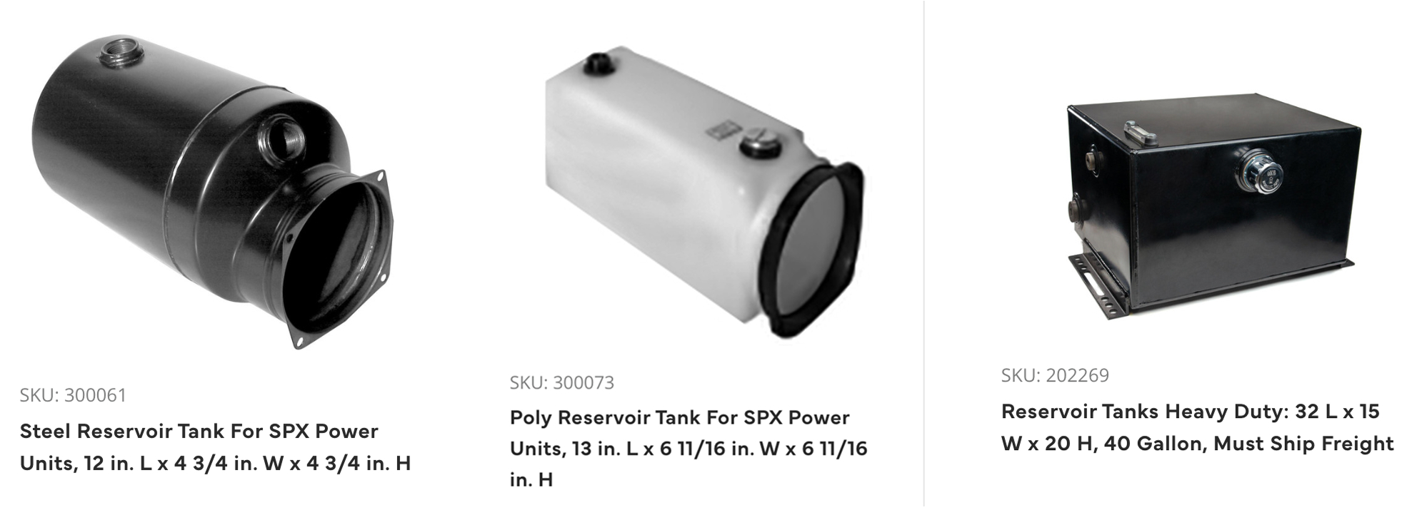
Reservoir Tank
The hydraulic tank acts as a reservoir, holding fluid, and is connected directly to the pump. It allows air bubbles to dissipate and contamination particles to settle, as well as allows the oil to cool while it is not circulating. A vented filter cap controls air flow, and a filter or strainer keeps contaminants out of the hydraulic fluid.
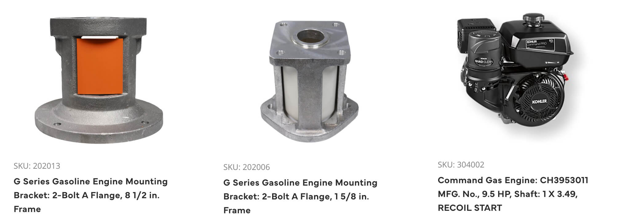
Pump and Engine
The hydraulic pump moves liquid from the reservoir tank through the system driven by an engine. Pump designs are typically two-stage, PTO or manual hydraulic, while the engine can be gas, diesel or electric depending on access to power, the horsepower needed and mounting style.
Pressure Gauges and Relief Valve
Once liquid is circulating, gauges can be used virtually anywhere in the system to monitor pressure. In addition, a relief valve controls the fluid pressure that powers the hydraulic cylinder; excess fluid is returned to the reservoir tank. This prevents pressure build-up and potential damage to equipment.
Valve Assembly
The hydraulic valve assembly controls the direction, pressure and flow rate of fluid through a hydraulic circuit. It regulates the speed of motors and movement of cylinders. Directional control valves are most common, controlling fluid flow from the pump to the cylinders and other system components.
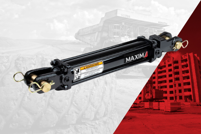
Cylinder
A hydraulic cylinder is an actuator that creates linear movement by converting hydraulic energy back to a mechanical movement – so it is the component that drives the work performed by mobile equipment. Cylinders can be used to lift, push, pull and press loads that require exceptional force.
Motor
Similar to cylinders, motors are actuators that converts hydraulic pressure and flow into movement, but it’s converted into torque and angular displacement (rotation) rather than linear motion. The amount of pressure and displacement of a motor will determine how much torque is produced while the amount of flow will determine the speed.
Flow Control Valve
The purpose of a flow control valve is to regulate the flow rate to motors and cylinders, thereby regulating the speed of those components.
Fluid Cooler
This unit removes the excess heat generated from the hydraulic fluid and helps to keep the temperature within a limited range before returning to the reservoir. Without proper cooling, the hydraulic system could overheat, causing component damage. Keeping the system properly cooled also extends hydraulic fluid life.
.png)
How Does A Hydraulic System Work?
A hydraulic cylinder is made up of a steel barrel, a piston connected to a piston rod that moves back and forth, and mounting accessories. A cylinder creates linear movement by converting hydraulic energy back to a mechanical movement. They are used in equipment to lift, push, pull and press loads that require exceptional force.
Hydraulic cylinders can be double-acting (pressurized oil moves it in either direction) or single-acting (pressurized oil extends the rod in one direction, and gravity pushes it back to its natural position).
To properly select a cylinder there are several factors to consider:
- Bore size (tube diameter) which determines how much force can be delivered at a given oil pressure
- Stroke, or how far the rod extends
- Piston rod diameter which is critical since it must apply that force without bending or buckling
- Speed determines the gallons per minute needed from the hydraulic pump and determines the correct port sizes
- How the cylinder will mount
We have hydraulic formulas and hydraulic calculators to make sure your cylinder is sized properly for the application. We at Bailey International are your trusted source for hydraulic products, system design help, as well as education and general support. After the sale, it’s the service and support that count!a
What is a Hydraulic Cylinder?

Build Custom with Bailey
Custom hydraulic and electronic solutions tailored to your unique needs. With expert engineering support and a comprehensive range of components, we streamline your project from design to delivery for seamless performance.