
How to Read Hydraulic Schematics
To the untrained eye, a hydraulic schematic looks like a chaotic jumble of shapes. However, to the engineers and technicians responsible for keeping mobile equipment running, these diagrams are a logical, universal language.
Whether you manage a fleet of construction vehicles or run a repair shop servicing agricultural equipment, the ability to decode hydraulic symbols is a critical operational asset. Understanding the flow of energy within your system allows you to diagnose issues faster, order the correct replacement parts, and minimize costly downtime.
Let us help you peel back the layers of complexity surrounding hydraulic diagrams.
The Logic Behind the Lines: ISO 1219-1
Before diving into specific components, it is helpful to understand the framework that governs these drawings. Hydraulic symbols are not random doodles; they are standardized globally, primarily through ISO 1219-1. This standard ensures that a schematic drawn for an excavator in Germany can be read and understood by a technician in the United States.
This standardization creates a common ground for the industry. It removes language barriers and focuses entirely on function. A symbol does not depict what a component looks like physically; rather, it depicts what the component does. A massive industrial pump and a small mobile pump might look very different on the shelf, but if they perform the same function, their symbol is identical. This abstraction is key to reading diagrams efficiently. Essentially, you are tracing function, not physical geometry.
To read a schematic, you must first recognize the "alphabet" of the language. While there are hundreds of variations, most diagrams are built from a few core categories of symbols.
Pumps and Motors
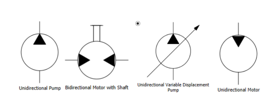
Rotary devices are almost always represented by circles. The distinction lies in the direction of the energy.
- Hydraulic Pumps: A pump converts mechanical energy into hydraulic energy. In a diagram, this is a circle with a triangular arrow pointing outwards. This indicates the fluid is being pushed out into the system. If the arrow is solid black, it signifies a hydraulic pump; an open outline would indicate a pneumatic pump.
- Hydraulic Motors: A motor performs the inverse operation, converting hydraulic pressure back into mechanical rotation. Consequently, its symbol is a circle with the triangular arrow pointing inwards, showing that the fluid pressure is entering the component to drive it.
Cylinders
Cylinders are perhaps the most intuitive symbols to read because they visually resemble the physical component. They are depicted as a rectangle (the barrel) with a T-shaped element inside (the piston and rod).
- Single-Acting Cylinders: These have a fluid port on only one side of the piston. The return stroke is often achieved by an external force (like gravity on a dump truck bed) or an internal spring.
- Double-Acting Cylinders: These feature ports on both sides of the piston, indicating that hydraulic fluid power drives the rod in both extension and retraction.
.png)
Valves
Valves direct, restrict, or stop the flow of fluid. They are the decision-makers of the circuit.
- Directional Control Valves: These are typically represented by a series of connected squares. Each square represents a specific "position" the valve can take (e.g., neutral, forward, reverse). Arrows inside the squares show the path fluid takes in that specific position.
- Pressure Control Valves: These are often single squares containing an arrow. A pilot line (dashed line) will show how the valve senses pressure to open or close. A common example is a Pressure Relief Valve, which is normally closed but opens to dump fluid to the tank if pressure exceeds a safety limit.
.png)
Types of Lines
Just as roads on a map vary from highways to side streets, the lines in a hydraulic schematic vary to indicate their purpose.
- Main Flow Lines: These are solid, continuous, bold lines. They represent the primary pipes, hoses, or tubes carrying the high-pressure fluid that does the actual work of moving cylinders or spinning motors.
- Pilot Lines: These are drawn as dashed or dotted lines. Think of these as "signal" wires. They carry fluid, but not to do heavy lifting. Instead, they transmit pressure signals to open valves, actuate gauges, or provide feedback to pumps.
- Drain Lines: Also dashed (though sometimes with a specific pattern depending on the standard), these lines carry leakage oil or control fluid back to the reservoir at low pressure.
- Enclosure Lines: A line made of long dashes and dots often indicates a component enclosure. This tells you that all the symbols inside that box are physically contained within a single manifold or housing.
.png)
Reading Complete Diagrams
Reading a full hydraulic diagram is a process of tracing the flow of energy. A helpful strategy is to start at the power source (the pump) and follow the main flow line.
- Start at the Reservoir: Every system begins with fluid storage, usually represented by an open-top box symbol at the bottom of the page.
- Follow the Pump: Trace the line up to the pump symbol. Note if it is a fixed or variable displacement pump (indicated by a diagonal arrow through the circle).
- Check the Controls: Follow the flow from the pump to the directional control valve. Is it an open center or closed center system? The arrows inside the valve symbol in the neutral position will tell you if fluid flows back to the tank or is blocked when the machine is idle.
- End at the Actuator: Finally, trace the lines to the cylinders or motors. This confirms what physical action results from the valve's movement. And remember, you’ll want to trace the full loop. What happens on the return to tank is just as relevant as the trip out to the actuator.
.png)
Troubleshooting with Schematics
The true value of reading schematics becomes apparent when equipment fails. Without a diagram, troubleshooting is often a game of guesswork. With a schematic, you can use logic to isolate the issue.
For example, if a cylinder is drifting (moving when it shouldn't), you can look at the schematic to see what is supposed to hold it in place. Is there a check valve? A counterbalance valve? The symbol will tell you exactly where the locking mechanism is located. If the diagram shows a pilot-operated check valve, you know to check that specific component for debris or seal failure, rather than replacing the entire cylinder. This targeted approach saves time and money, getting your fleet back in operation faster.
While standard symbols cover the vast majority of hydraulic systems, the specific needs of modern transportation, construction, and agricultural equipment often require specialized configurations. Off-the-shelf components do not always fit the unique space or performance constraints of a customized machine.
This is where the abstraction of symbols meets the reality of engineering. You might design a circuit on paper using standard ISO symbols, but realizing that circuit might require a custom manifold block to fit a tight chassis, or a bespoke cylinder to handle specific load requirements.
At Bailey International, we bridge the gap between theoretical design and physical application. Our engineering team can look at a schematic, or help you create one, and develop custom hydraulic solutions that integrate seamlessly with your existing operations. Whether you need to combine multiple valve functions into a single, compact manifold or require a cylinder with unique mounting geometry, we ensure the physical product matches the logical intent of your design.


Shop
Hydraulics & Electronics
Bailey produces the highest quality hydraulic and electronic parts for diverse applications including manufacturing, automotive, construction, agriculture, forestry and OEM.


SKU: 325052


Build With Bailey
Custom hydraulic solutions designed to meet your unique needs. From expert engineering support to a wide range of components, we streamline your project from design to delivery.